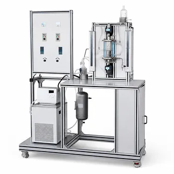
RTD analysis is non-negotiable for gas-continuous impinging streams reactors because their performance hinges on a highly localized, intense mixing zone that deviates wildly from ideal flow models. You can’t predict conversion or selectivity without it. In pilot plants, this is modeled by decomposing the reactor into four distinct zones and experimentally mapping the flow with tracer studies, allowing engineers to diagnose backmixing and bypassing before a failed scale-up attempt.
Impinging stream reactors create a unique hydrodynamic fingerprint where the energy dissipation in the impingement zone dictates the entire reaction outcome. The core challenge is that standard RTD theory applies to homogeneous systems, yet GIS reactors are inherently multiphase. Pilot-scale RTD analysis bridges this gap, providing an empirical, zone-based model of non-ideal flow that is essential for quantifying the deviation from ideal behavior and creating a reliable blueprint for scaling up gas-continuous reactions.
The Fundamental Role of RTD in Impinging Streams Reactors
The primary reason to analyze RTD is to connect fluid mechanics to chemical performance. In a gas-continuous impinging streams (GIS) reactor, the flow pattern is the reactor. Without mapping the residence time distribution, you are operating blindly, unable to predict whether reactants have enough time to convert or if they are bypassing the reaction zone entirely.
Predicting Conversion and Selectivity in a Non-Ideal World
The RTD curve is not just a diagnostic; it’s a predictive model. It allows you to calculate the maximum possible conversion and expected product selectivity by showing the time history of fluid elements in the reactor.
In a GIS reactor, the reaction largely happens in a small, high-turbulence zone. If fluid elements leave this zone too quickly—or linger too long in stagnant areas—your selectivity for a desired intermediate product can plummet, leading to over-reaction or side products. Analyzing the RTD quantifies these risks.
Diagnosing Flow Pathologies Unique to Impingement
Impinging streams are designed to create a controlled collision, but maldistribution can create severe non-idealities. RTD analysis on a pilot plant is the only reliable way to detect these problems before they become catastrophic in a commercial unit.
The shape of the experimental RTD curve, specifically the density function f(θ), acts as a diagnostic fingerprint. An early peak indicates bypassing, where a portion of the feed gas shorts through the reactor without mixing. A long, decaying tail reveals stagnant regions or recirculation zones, where product gets trapped and degrades. These are not theoretical flaws; they are real physical phenomena that tank reactor performance.
Modeling the GIS Reactor: A Zone-Based Approach
You cannot model a GIS reactor with a simple Continuous Stirred Tank Reactor (CSTR) or Plug Flow Reactor (PFR) model. Its behavior is too complex. The standard pilot-plant modeling approach divides the reactor into a series of physical zones, each contributing a distinct signature to the overall RTD.
Deconstructing the Reactor into Four Zones
The fluid journey is modeled as a sequence through four distinct hydrodynamic regions. This zonal decomposition turns an unmanageably complex problem into a solvable network of simpler elements.
The journey begins in the acceleration zone, where the gas feed is accelerated through the inlet nozzles to high velocity. This section behaves with a narrow distribution, approaching plug flow. Next is the critical impingement zone, the heart of the reactor where streams collide. This zone is modeled as a region of intense micromixing with high energy dissipation, often approximating a small, perfectly mixed CSTR. The reaction then enters the deceleration/fall zone, where momentum dissipates and flow patterns are transitional. Finally, products settle in the collection zone, a plenum that can introduce significant backmixing, often modeled as a larger CSTR.
Experimentally Verifying the Model with Tracer Injection
The theoretical zone model is just a hypothesis until it’s validated. Pilot-plant students and engineers introduce an inert tracer (a step or pulse injection) at the inlets and measure its concentration leaving the reactor.
This generates the experimental RTD curve. The mean residence time and the shape of the curve are then calculated to verify the model. If the physical system matches the zone model, the experimental and theoretical curves will align. A mismatch forces a re-evaluation of the zonal assumptions, revealing the true, non-ideal flow behavior at play.
Translating Theory to Pilot-Plant Reality
Taking an RTD from a textbook to a working pilot plant requires rigorous experimental discipline. Three non-negotiable conditions must be verified for your data to be physically meaningful rather than a collection of artifacts.
Verifying Stationarity and Turbulent Averaging
The system must be at a steady state. The normalized concentration response at the outlet must be independent of the exact moment you inject the tracer.
This is particularly challenging in turbulent flows dominated by large, slow eddies. You can achieve stationarity by ensuring a high length-to-diameter ratio in the reactor, which statistically averages out turbulence effects. Alternatively, a mechanical agitator in the collection zone can force the issue. The practical test is simple: run the step response experiment twice. If the consecutive E-curves are identical, the condition of stationarity is met.
Confirming Linearity and Tracer Fidelity
The tracer response must be directly proportional to its concentration. You cannot assume this is true. Linearity is verified by running two experiments at different step-input magnitudes. If you normalize the response curves by the final concentration and they overlap perfectly, the system is linear within that range.
Beyond linearity, the tracer must also behave identically to the process fluid. This is the most critical hurdle in multiphase systems like GIS reactors. A gas-phase tracer can’t adsorb onto particles, diffuse into a stagnant film, or condense. If it does, you’re measuring the tracer’s personal journey, not the reactant’s. The wrong tracer choice produces a dangerously misleading RTD and invalidates the entire scale-up exercise.
Interpreting Variance to Quantify Backmixing
The raw curve is visually useful, but the real quantitative power comes from its second moment: variance. A variance value quantifies the degree of backmixing on a spectrum from zero (ideal plug flow) to one (a single ideal CSTR).
In a pilot plant, a variance close to zero, measured on the impingement section in isolation, validates a near-PFR design. A high variance in the overall reactor, however, indicates the collection zone is dominating the flow pattern with significant macromixing. Comparing the variance of your GIS reactor to ideal limits gives you a single, powerful number to describe the non-ideality of your physical system.
Understanding the Trade-offs and Limitations
No analytical method is a silver bullet. Applying conventional RTD theory to a gas-continuous impinging streams reactor presents specific trade-offs you must acknowledge to avoid costly misinterpretations.
The Homogeneous Assumption vs. Multiphase Reality
The fundamental limitation is that classical RTD theory is rigorously valid only for homogeneous, single-phase systems. An impinging streams reactor is built on heterogeneous gas-solid or gas-droplet interactions.
The gas-phase RTD tells you how the continuous gas phase flows. It does not automatically describe the contact time of solid catalyst particles or liquid droplets. If there is significant mass transfer resistance between the gas and the dispersed phase, the gas RTD becomes decoupled from the true reaction history. Pilot plants are essential precisely to identify the threshold where this decoupling breaks the model, making standard tracer probes unreliable without complementary contact-time distribution studies.
Scale-Up Risks and the Zone Model's Reach
The zonal model decomposes the reactor into idealized building blocks. This is an empirical representation, not a first-principles CFD solution. The danger in scale-up is that the boundaries between these zones shift or their relative volumes change non-linearly with reactor size.
The intense turbulence in the impingement zone, for example, is highly scale-dependent. A zone that is a perfectly mixed CSTR in the pilot plant might split into multiple flow regimes in a larger unit. Relying on RTD to provide bounds for outlet composition is the safe approach; believing a fixed-parameter zone model will perfectly predict a commercial-scale reactor is a mistake. The model constrains your predictions, it doesn't eliminate uncertainty.
Making the Right Choice for Your Pilot-Plant Goal
Your analytical strategy should be tailored to the specific risk you are trying to retire. The RTD can answer several different questions, but only if you design the experiment for a specific outcome.
- If your primary focus is validating a reactor design before commercial scale-up: Focus on the variance and detectability of bypassing. Use the RTD to bound the worst-case deviation from plug flow and ensure your product specification can handle that degree of backmixing, not just the ideal case.
- If your primary focus is troubleshooting a yield or selectivity problem in an existing pilot unit: Zero in on the shape of the density function f(θ). A tail on the curve points you directly to stagnant zones or recirculation in the collection zone; an early peak pinpoints a feed maldistribution causing bypassing.
- If your primary focus is building a predictive first-principles model for a complex reaction network: Run both single-phase and multiphase tracer tests. Contrast the gas RTD against a dispersed-phase residence time to map the mass transfer resistance explicitly, defining the boundaries where your model transitions from valid to invalid.
An impinging streams reactor’s value is its ability to confine a reaction to a high-intensity mixing zone—and RTD analysis is the only tool that allows you to prove it’s actually doing that at scale.
Summary Table:
| Reactor Zone | Hydrodynamic Behavior | Flow Model / Representation |
|---|---|---|
| Acceleration | Gas accelerated through inlet nozzles | Plug Flow (PFR-like) |
| Impingement | Intense mixing & energy dissipation | Small CSTR |
| Deceleration | Momentum dissipates | Transitional flow |
| Collection | Product settling, potential backmixing | Large CSTR |
Scale Up Your Chemical Engineering Research with LABPARK
Accurate reactor modeling requires high-precision hardware. LABPARK provides state-of-the-art Educational and Vocational Unit Operations Pilot Plants in chemical engineering, bioprocess & biotech, and environmental & water treatment. We empower universities, research institutes, and enterprises to bridge the gap between theoretical calculations and real-world industrial application.
Ready to upgrade your laboratory capabilities? Contact us today to find the perfect pilot plant solution for your institution!
Related Products
- Residence Time Distribution and Reactor Flow Characteristics Determination Educational Pilot Plant
- Gas Phase Mixing and Residence Time Distribution Determination Educational Unit Operations Pilot Plant
- Micro-Scale Gas-Solid Catalytic Reaction Educational Pilot Plant
- Dual-Drive Stirred Gas-Liquid Mass Transfer Coefficient Determination Pilot Plant
- 100L Continuous Loop Hydrogenation Educational Unit Operations Pilot Plant
People Also Ask
- Why is temperature regulation via a cooling jacket a critical feature in CSTR pilot plants used for laboratory training?
- What is the significance of CSTR chaotic behavior? Master Reactor Safety
- What parameters to monitor transitioning from Batch to CSTR? Master Pilot Plant Setup
- How does steady-state multiplicity affect the operation and safety of exothermic reactions within a CSTR pilot plant? - Guide
- How does CSTR cooling jacket design influence stability? Control reactor oscillations.