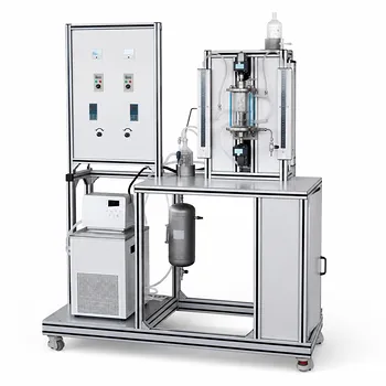
Here’s the definitive standard configuration. For a single-impeller gas-liquid stirred tank in a unit operations laboratory, the reactor must have a liquid height equal to the vessel diameter (H/dR = 1). The impeller diameter should be 40-50% of the vessel diameter (dA/dR = 0.4-0.5), positioned at a clearance off the bottom of 33-50% of the vessel diameter (hA/dR = 0.33-0.5). To prevent vortexing and ensure proper mixing, the vessel must be equipped with four 90° baffles, each precisely one-twelfth the vessel diameter in width, mounted with a gap from the wall equal to one-sixth of their width.
A standardized geometry is non-negotiable for teaching representative industrial mixing. The specific ratios for impeller position and vessel dimensions prevent a flooded impeller, but the four baffles are the true linchpin—they convert wasteful tangential swirling into the powerful vertical flow pattern essential for gas dispersion.
Fixing the Geometry: Preventing a Flooded Impeller
Before gas dispersion can even be discussed, the liquid-phase hydrodynamics must be nailed. The ratios you choose dictate whether your impeller simply spins in place or actually loads gas.
The Liquid Height Sweet Spot
The H/dR = 1 rule is about creating a consistent, predictable flow path. A liquid height equal to the tank diameter prevents short-circuiting and ensures that the downward flow from the baffles reaches the impeller with enough momentum.
Without this aspect ratio, you might create a stable secondary circulation loop above the impeller that traps gas. This makes scale-up calculations from your lab data unreliable.
Impeller Diameter and Power Input
An agitator-to-vessel diameter ratio (dA/dR) of 0.4 to 0.5 is a compromise between torque and fluid velocity. A larger diameter pushes more fluid, crucial for dragging gas bubbles down, but requires more power.
A smaller diameter might fail to create a sufficient low-pressure zone behind the blades to effectively draw gas from the sparger. You end up with the gas simply bubbling straight to the surface at the shaft.
Clearance from the Tank Bottom
The hA/dR ratio of 0.33 to 0.5 positions the impeller close enough to the sparger ring to capture the freshly introduced gas. If the impeller is too high, the gas plume can bypass the impeller’s dispersion zone entirely.
If the clearance is too low, the flow pattern under the impeller becomes restricted. This chokes the pump and reduces the impeller’s ability to pull liquid and gas from below, once again leading to flooding.
Mastering the Art of Baffling
Baffles are not optional accessories. They are the primary mechanism that changes the fluid motion from a lazy tea-cup swirl into a high-energy regime capable of tearing gas into fine bubbles.
The Standard Baffle Configuration
The four 90° baffles are spaced equidistantly around the vessel wall. Each baffle’s width is precisely dR/12. This isn't an arbitrary number; it's the minimum surface area required to fully stop the solid-body rotation of the fluid in a standard tank.
Too narrow, and a swirling vortex persists, pulling gas down the shaft in large, useless slugs. Too wide, and you create dead zones behind the baffles where no mixing occurs.
The Critical Wall Offset
Do not weld the baffles directly to the vessel wall. The gap—specifically one-sixth of the baffle width—is a crucial design detail. This offset allows liquid to sweep behind the baffle, preventing stagnant zones where solids can settle or where reaction intermediates can degrade.
This sweeping action also creates small, intense eddies as fluid shears around the baffle edge. These eddies are a secondary mechanism for bubble breakup, complementing the work done at the impeller blades.
The Hidden Variable: Agitation Scale and Gas Dispersion
Knowing the fixed geometry is step one. But the true goal is to achieve a specific dispersion regime, which your students must be able to identify and manipulate.
Moving Beyond a Flooded Impeller
The supplementary reference defines Scale 0 as a flooded state, a condition completely unacceptable for a teaching lab because it’s irrelevant to industrial operation. The standard geometry is designed precisely to keep you out of this zone.
If you observe large gas bubbles simply bubbling through with no radial distribution, your geometry or impeller speed is wrong. You have failed to establish the gas-filled cavities on the back of the impeller blades that are required for proper dispersion.
The Target Regime for a Unit Ops Lab
For a laboratory exercise, you should target Scales 3-5, representing moderate dispersion. At this level, fine bubbles are driven to the wall, recirculated back to the impeller, and a dynamic balance between dispersion and coalescence is visually apparent.
Scales 6-10 are for true mass-transfer-critical industrial processes, where power costs are secondary to reaction speed. Unless you are studying gas-liquid reaction kinetics at their performance limit, forcing the unit to these extreme scales just adds unnecessary motor load without extra teaching value.
Understanding the Trade-offs
A standard setup is a model system, not a perfect replica of every industrial reactor. You must know its blind spots.
The Flat-Bottom Assumption
This standard geometry inherently assumes a flat-bottomed vessel, which is common in glass lab reactors. Many industrial reactors use a dished bottom to improve solids suspension and drainage. The flow pattern near your flat bottom will have a low-velocity zone in the corner that a dished head would eliminate. Warn your students about this scale-up discrepancy.
Fixed Geometry, Fixed Performance Map
The fixed dA/D and baffle design locks you into a specific power-draw behavior and flow pattern. You cannot optimize for radically different fluids, like a highly viscous broth, with this single configuration. The lab reactor teaches the principles of a water-like system; applying these exact ratios to a non-Newtonian fluid will yield poor results, a lesson in itself.
How to Apply This in Your Laboratory Setup
Start with the standard as your unshakeable baseline, then adapt your teaching targets based on the specific learning objective of the session.
- If your primary focus is measuring gassed power draw: Use the exact standard geometry. The baffle gap and impeller size are critical here, as any vortex at the shaft will make your power readings erratic.
- If your primary focus is visualizing mass transfer regimes: Start at Scale 3-5 to show moderate dispersion, then briefly ramp speed to demonstrate the flooding-to-complete dispersion transition. The standard baffles make this transition sharp and observable.
- If your primary focus is demonstrating cold-flow hydrodynamics: The standard setup is a perfect, repeatable baseline. Use a ding to highlight how the baffle wall-offset eliminates stagnant accumulation—a subtle but powerful industrial design lesson.
Adhering to this single, well-defined configuration transforms the reactor from an unpredictable black box into a predictable, teachable system.
Summary Table:
| Parameter | Standard Ratio | Key Function |
|---|---|---|
| Liquid Height ($H/d_R$) | 1.0 | Prevents gas trapping & short-circuiting |
| Impeller Diameter ($d_A/d_R$) | 0.4 - 0.5 | Balances torque and gas dispersion |
| Impeller Clearance ($h_A/d_R$) | 0.33 - 0.5 | Captures gas from the sparger |
| Baffle Count & Width | 4 (90° apart), width = $d_R/12$ | Converts tangential swirl to vertical flow |
| Baffle Wall Offset | 1/6 of baffle width | Eliminates stagnant zones & solids buildup |
Bring Industrial-Scale Precision to Your Unit Operations Lab
Are you looking to equip your laboratory with reliable, industry-standard training systems? LABPARK provides state-of-the-art Educational and Vocational Unit Operations Pilot Plants across chemical engineering, bioprocess & biotech, and environmental & water treatment sectors. Developed specifically for universities, research institutes, and enterprises, our pilot plants ensure precise scaling, robust safety features, and maximum educational value.
Ready to upgrade your department's capabilities? Contact LABPARK today to receive a tailored solution for your laboratory!
Related Products
- Dual-Drive Stirred Gas-Liquid Mass Transfer Coefficient Determination Pilot Plant
- Micro-Scale Gas-Solid Catalytic Reaction Educational Pilot Plant
- Methane Cracking Educational Unit Operations Pilot Plant
- Multi-Stage Stirred Tanks in Series Residence Time Distribution and Mixing Performance Determination Educational Pilot Plant
- Agitation and Mixing Educational Unit Operations Pilot Plant
People Also Ask
- How does column packing affect absorption intensification, and how is it evaluated experimentally?
- Why Compare Membrane-Reservoir Models with Pilot Plant Data? Ensure Successful Process Scale-Up
- Why is pilot plant gas absorption lower than isothermal model predictions? Interfacial heating explained.
- Which interphase forces dominate gas dispersion in stirred reactors? Master Gas Holdup Models
- What operational factors must be considered in viscous gas-liquid mass transfer? Pilot Plant Guide