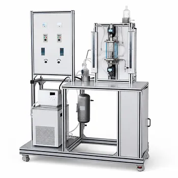
Here is the crucial empirical reality you must build your experimental protocol around: In a mechanically agitated gas-liquid reactor pilot plant, the introduction of gas sparging typically perturbs the heat transfer coefficient by no more than 25% to 30% compared to an ungassed system, and this effect diminishes significantly at higher agitation speeds. This means that while sparging is a necessary variable to control, the dominant driver of heat transfer remains the mechanical power input from the impeller.
The deep operational insight is that you should not view gas sparging as a primary tool for controlling heat transfer in a stirred tank. Instead, treat it as a modifier that creates a bounded zone of uncertainty. Your experimental design must therefore prioritize mechanical mixing intensity (Reynolds number) to set the baseline heat transfer regime and then meticulously map the sparging effect as a secondary, yet critical, perturbation that decays with impeller speed.
The Physics of Sparging: More Than Just Bubbles
To factor sparging into your operations, you must first detach from the idea that the gas simply provides cooling. Its influence is far more nuanced, acting through fluid dynamics rather than direct sensible heat exchange.
Sparging Reshapes the Boundary Layer
In a stirred tank, heat transfer is governed by convection, characterized by the Nusselt number. Without mixing, you are in a conduction-limited regime where the Nusselt number is close to 1.
When you mechanically agitate, you drive the Nusselt number up to values between 100 and 1000 by shredding the thermal boundary layer on cooling surfaces. Introducing gas sparging adds a new variable. Bubble-induced turbulence generates micro-eddies at the heat transfer surface.
The resulting heat transfer coefficient is closely tied to the Sauter mean diameter of your bubbles. Sparger designs that generate a high population of sub-2.5-mm bubbles, like a sintered plate, maximize this micro-turbulence effect and enhance local heat transfer more effectively than a single-nozzle sparger producing large, fast-rising bubbles.
The Critical Interplay with Mechanical Agitation
This is where the 25-30% rule becomes your experimental compass. At low impeller speeds, the gas sparging rate can significantly influence the overall mixing and heat transfer because the gas provides a large fraction of the total energy input.
However, as you increase agitation speed, the impeller’s flow field becomes dominant. The high-shear zone around a flat-blade turbine cavitates the gas, directly controlling bubble size and dispersion. The impeller, not the sparger, now dictates the fluid dynamics. The gas sparging effect on the heat transfer coefficient decays, becoming a secondary perturbation that is measurable but no longer the primary lever.
Operational Pitfalls to Avoid
Translating this physics into a pilot plant protocol means guarding against conditions where the standard correlations break down.
The Flooding Limit
A mechanically agitated system is ideal because it allows you to independently control gas dispersion via impeller configuration, like adding a secondary impeller to re-disperse gas. But if you push the gas flow rate too high relative to the impeller speed, you will flood the impeller.
When flooded, the impeller rotates in a gas pocket, power draw crashes, and the mixing Reynolds number plummets. Your heat transfer coefficient will not just vary by 25-30%; it will collapse. Your operational envelope must always stay below the flooding curve for your specific impeller type.
The Non-Condensable Trap
If your reaction involves condensable vapors or you are using the reactor jacket as a condenser, sparging with an inert gas creates a hidden problem. The non-condensable gas accumulates at the cooling surface, forming a diffusion barrier that severely throttles heat transfer.
Your standard liquid-phase heat transfer correlation will be wildly inaccurate here. To accurately model this in your pilot plant data, you must switch to methods like the Silver-Bell-Ghaly or Colburn-Hougen approach, which account for the reduction in the condensation coefficient due to gas-phase mass transfer resistance.
The Slug Flow Disconnect
Be aware of a sparger-design paradox, particularly in taller reactor sections. At low gas velocities in a bubble column regime, a porous plate sparger yields higher gas holdup and better heat transfer than a single nozzle. However, once you enter a slug flow regime at high gas velocities, the sparger design ceases to matter—large slugs dominate, and the initial bubble size is irrelevant. Your experimental interpretation must acknowledge that the sparger’s influence itself is flow-regime dependent.
Translating Theory into a Robust Experimental Protocol
Your job is to generate scalable data, not just run the reactor. Here is how to modify your experimental plan based on your primary goal.
- If your primary focus is generating a scale-up correlation: Vary agitation speed at several fixed gas flow rates. Focus on the high-speed region where the sparging effect is minimal. Your semiempirical correlation must explicitly include a gas holdup term ($\epsilon_g$) or a velocity ratio to capture that bounded 25-30% perturbation on the liquid-phase convective term.
- If your primary focus is mapping multiphase heat transfer fundamentals: Start at a low, constant agitation speed and vary the sparger type (e.g., single nozzle vs. sintered plate) across a range of gas flow rates. This decouples the impeller’s dominance and lets you isolate the direct relationship between bubble size distribution (Sauter mean diameter) and the Nusselt number.
- If your primary focus is a low-gas-flow, dead-end reaction: You are in the riskiest zone for heat transfer control. Do not rely on sparging for mixing. Your protocol must confirm, via power draw measurement, that the impeller is not flooded and is achieving the turbulent Reynolds number required to suspend the catalyst and maintain your target Nusselt number.
Your pilot plant is a mathematical model made of metal and glass; by precisely understanding the 25-30% coupling window between the sparger and the impeller, you turn thermal uncertainty into a quantified, manageable variable.
Summary Table:
| Operational Variable / Regime | Impact on Heat Transfer Coefficient | Operational Action & Recommendation |
|---|---|---|
| Gas Sparging Rate | 25% to 30% perturbation (diminishes at high agitation speeds) | Prioritize mechanical mixing (Reynolds number) to set the baseline regime. |
| Bubble Size (Sauter Mean) | Sub-2.5-mm bubbles maximize micro-turbulence and heat transfer | Use sintered plate spargers instead of single-nozzle designs at low agitation. |
| Impeller Flooding Limit | Severe collapse in heat transfer due to gas pocketing around impeller | Design the operational envelope to stay strictly below the flooding curve. |
| Non-Condensable Gases | Drastic reduction due to gas-phase mass transfer resistance | Apply the Silver-Bell-Ghaly or Colburn-Hougen modeling approach. |
| Slug Flow Regime | Sparger design influence ceases; large gas slugs dominate dynamics | Focus experimental interpretation on flow-regime-dependent limits. |
Elevate Your Chemical Engineering Research & Training with LABPARK
Achieving precise control over multiphase heat transfer and mixing regimes requires highly reliable, industry-grade equipment.
LABPARK provides premium Educational and Vocational Unit Operations Pilot Plants in chemical engineering, bioprocess & biotech, and environmental & water treatment. Tailored for universities, research institutes, and enterprises, our advanced pilot systems empower you to accurately model gas sparging, optimize agitation parameters, and generate scalable experimental data.
Ready to enhance your lab's capabilities? Contact our expert team today to find the perfect pilot plant configuration for your application!
Related Products
- Dual-Drive Stirred Gas-Liquid Mass Transfer Coefficient Determination Pilot Plant
- Fixed-Bed Chemical Reaction and Gas Dust Tar Removal Unit Operations Pilot Plant
- Methane Cracking Educational Unit Operations Pilot Plant
- Fixed Bed Gas Solid Catalytic Reaction Educational Pilot Plant
- Agitation and Mixing Educational Unit Operations Pilot Plant
People Also Ask
- How does column packing affect absorption intensification, and how is it evaluated experimentally?
- Why Compare Membrane-Reservoir Models with Pilot Plant Data? Ensure Successful Process Scale-Up
- Why is pilot plant gas absorption lower than isothermal model predictions? Interfacial heating explained.
- Which interphase forces dominate gas dispersion in stirred reactors? Master Gas Holdup Models
- What operational factors must be considered in viscous gas-liquid mass transfer? Pilot Plant Guide