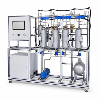
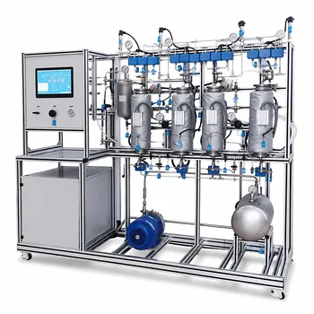
In a gas absorption pilot plant, calculate the flow-rate change by tracking an unchanged carrier-gas component. Determine the inert-gas molar flow from the inlet volumetric flow, pressure, temperature, and composition; use that same inert flow with the outlet composition to calculate the reduced total gas flow. The difference between inlet and outlet solute molar flow is the absorption rate.
Core takeaway: The carrier gas is the tie component for the balance. If it is neither absorbed nor generated, its molar flow remains constant, while removal of the soluble gas reduces the total gas molar and volumetric flow rates.
Establish the Material-Balance Basis
Identify the gas components
Let:
- (A) = soluble solute being removed, such as ammonia, sulfur dioxide, or hydrogen chloride
- (I) = inert carrier gas, such as air or nitrogen
- (G_{\text{in}}), (G_{\text{out}}) = total gas molar flow rates
- (y_A), (y_I) = gas-phase mole fractions
- (Q) = gas volumetric flow rate
For dilute gas mixtures, reported volumetric fractions are usually treated as mole fractions because, for ideal gases, volume fraction equals mole fraction at the same temperature and pressure.
Use a consistent basis
Use either:
- mol/s or kmol/h for molar balances, or
- kg/s or kg/h for mass balances.
Do not mix actual volumetric flow with standard volumetric flow without correcting for temperature and pressure. Also use absolute temperature and absolute pressure in the gas law.
Select the tie component
The inert carrier is the most useful reference because its quantity is normally unchanged through the absorber:
[ \dot n_{I,\text{in}}=\dot n_{I,\text{out}} ]
This assumption is valid only if the carrier gas is not absorbed, generated, consumed, condensed, or lost through leakage.
Calculate the Inlet Gas Flow
Convert inlet volume to total molar flow
For an ideal gas, calculate the inlet total gas molar flow using:
[ \dot n_{G,\text{in}}
\frac{P_{\text{in}}Q_{\text{in}}}{Z_{\text{in}}RT_{\text{in}}} ]
where:
- (P_{\text{in}}) = absolute inlet pressure
- (Q_{\text{in}}) = actual inlet volumetric flow rate
- (T_{\text{in}}) = absolute inlet temperature
- (R) = gas constant
- (Z_{\text{in}}) = compressibility factor, often approximated as 1 for dilute gases at moderate pressure
If the flow meter reports a standard volumetric flow, use the corresponding standard pressure and temperature instead of the actual tower conditions.
Calculate inert-gas flow
If the inlet inert-gas mole fraction is (y_{I,\text{in}}):
[ \dot n_I
y_{I,\text{in}}\dot n_{G,\text{in}} ]
Equivalently, if the inlet solute mole fraction is (y_{A,\text{in}}) and the gas contains only solute and inert carrier:
[ y_{I,\text{in}}=1-y_{A,\text{in}} ]
Therefore:
[ \dot n_I
(1-y_{A,\text{in}})\dot n_{G,\text{in}} ]
Calculate inlet solute flow
The inlet solute molar flow is:
[ \dot n_{A,\text{in}}
y_{A,\text{in}}\dot n_{G,\text{in}} ]
This is the quantity that will be compared with the outlet solute flow to determine removal.
Calculate the Outlet Gas Flow
Apply the inert-gas balance
Because the inert carrier passes through the absorber unchanged:
[ \dot n_{I,\text{out}}
\dot n_{I,\text{in}}
\dot n_I ]
If the outlet inert-gas mole fraction is measured as (y_{I,\text{out}}), the total outlet gas molar flow is:
[ \dot n_{G,\text{out}}
\frac{\dot n_I}{y_{I,\text{out}}} ]
For a gas containing only inert carrier and residual solute:
[ \dot n_{G,\text{out}}
\frac{\dot n_I}{1-y_{A,\text{out}}} ]
This is the key calculation. The outlet total molar flow is not generally equal to the inlet total molar flow because solute has been removed.
Calculate outlet solute flow
Using the measured outlet solute concentration:
[ \dot n_{A,\text{out}}
y_{A,\text{out}}\dot n_{G,\text{out}} ]
If other nonabsorbed gas components are present, use the complete outlet composition:
[ \dot n_{G,\text{out}}
\frac{\dot n_I}{y_{I,\text{out}}} ]
The inert fraction must include the actual composition basis used for the measurement, such as dry gas or wet gas.
Determine the absorbed solute rate
Assuming no solute is generated or consumed by reaction in the gas phase:
[ \dot n_{A,\text{absorbed}}
\dot n_{A,\text{in}}
\dot n_{A,\text{out}} ]
The corresponding mass absorption rate is:
[ \dot m_{A,\text{absorbed}}
\dot n_{A,\text{absorbed}}M_A ]
where (M_A) is the solute molecular weight.
Calculate removal efficiency
The fraction removed is:
[ \eta_A
\frac{\dot n_{A,\text{in}}-\dot n_{A,\text{out}}} {\dot n_{A,\text{in}}} ]
The percentage removal is:
[ %,\text{removal}
100\eta_A ]
This is normally the most direct performance measure for a scrubbing column.
Convert Molar Flow Changes to Volumetric Flow Changes
Use the outlet gas law
Once the outlet total molar flow is known, calculate the outlet volumetric flow at the outlet tower conditions:
[ Q_{\text{out}}
\frac{\dot n_{G,\text{out}}Z_{\text{out}}RT_{\text{out}}} {P_{\text{out}}} ]
For an ideal gas:
[ Q_{\text{out}}
\frac{\dot n_{G,\text{out}}RT_{\text{out}}} {P_{\text{out}}} ]
The outlet volume can be greater or smaller than the inlet volume. Solute removal tends to reduce total moles, while temperature increase or pressure decrease tends to increase volume.
Separate composition effects from condition effects
A change in volumetric flow has two possible causes:
- Composition effect: absorption changes the total number of gas moles.
- Thermodynamic effect: temperature or pressure changes alter the gas volume.
For example, even if the gas molar flow decreases, heating in the column may partly offset that reduction in measured volumetric flow.
Relate inlet and outlet flow directly
Combining the ideal-gas relationships gives:
[ \frac{Q_{\text{out}}}{Q_{\text{in}}}
\frac{\dot n_{G,\text{out}}}{\dot n_{G,\text{in}}} \frac{T_{\text{out}}}{T_{\text{in}}} \frac{P_{\text{in}}}{P_{\text{out}}} ]
For nonideal gases, include the compressibility-factor ratio:
[ \frac{Q_{\text{out}}}{Q_{\text{in}}}
\frac{\dot n_{G,\text{out}}}{\dot n_{G,\text{in}}} \frac{Z_{\text{out}}}{Z_{\text{in}}} \frac{T_{\text{out}}}{T_{\text{in}}} \frac{P_{\text{in}}}{P_{\text{out}}} ]
This equation clearly shows why inlet and outlet flow meters may report different volumetric rates even when the carrier-gas molar flow is unchanged.
Complete the Liquid-Side Balance
Write the solute balance around the entire column
At steady state, the solute balance is:
[ \dot n_{A,\text{gas,in}} + \dot n_{A,\text{liquid,in}}
\dot n_{A,\text{gas,out}} + \dot n_{A,\text{liquid,out}} ]
If the entering liquid contains no solute:
[ \dot n_{A,\text{liquid,out}}
\dot n_{A,\text{gas,in}}
\dot n_{A,\text{gas,out}} ]
This result should agree with the gas-side absorbed solute rate.
Account for solvent flow
If the solvent is nonvolatile and does not react:
[ \dot n_{S,\text{liquid,in}}
\dot n_{S,\text{liquid,out}} ]
In practical systems, however, water or another solvent may evaporate into the gas. If solvent vaporization is significant, the solvent balance must include that loss:
[ \dot n_{S,\text{liquid,in}}
\dot n_{S,\text{liquid,out}} + \dot n_{S,\text{gas,out}}
\dot n_{S,\text{gas,in}} ]
A wet-gas correction may therefore be necessary when comparing gas compositions or flow rates.
Use mass fractions when operating data are reported that way
If liquid composition is reported as a solute mass fraction (w_A), the liquid solute mass flow is:
[ \dot m_{A,\text{liquid}}
w_A\dot m_{\text{liquid}} ]
For a steady absorber, the liquid-side solute increase should equal the gas-side solute removal:
[ \dot m_{A,\text{liquid,out}}
\dot m_{A,\text{liquid,in}}
\dot m_{A,\text{gas,in}}
\dot m_{A,\text{gas,out}} ]
This is particularly useful for aqueous ammonia, acid-gas scrubbing, and other systems where liquid concentrations are measured directly.
Interpret the Column Performance
Compare measured compositions with equilibrium
Gas absorption is driven by the difference between the actual gas-liquid condition and equilibrium. Vapor-liquid equilibrium data relate the solute partial pressure in the gas to its concentration in the liquid at the operating temperature and pressure.
For dilute systems, an equilibrium relation may be written in the form:
[ y_A^*=m x_A ]
where:
- (y_A^*) = gas-phase solute fraction at equilibrium
- (x_A) = liquid-phase solute fraction
- (m) = equilibrium slope
The material balance determines how much solute was removed; the equilibrium relation helps explain whether the column had sufficient mass-transfer driving force.
Use the operating-line relationship
For a steady counter-current absorber, a simplified mass-balance relationship can be expressed using solute weight fractions:
[ \frac{w_{A,\text{gas,out}}-w_{A,\text{gas,in}}} {w_{A,\text{liquid,out}}-w_{A,\text{liquid,in}}}
-\frac{F_{\text{liquid}}}{F_{\text{gas}}} ]
The negative sign reflects the opposite composition changes: solute decreases in the gas while it increases in the liquid.
A high liquid-to-gas flow ratio generally provides greater solvent capacity and stronger absorption, but it also increases liquid circulation and downstream utility requirements.
Understanding the Trade-offs
Do not assume total gas flow is constant
Holding total gas flow constant after absorption gives an incorrect solute balance unless the flow is independently controlled or another gas component replaces the removed solute.
The correct approach is to conserve the inert carrier and recalculate the total outlet flow from the outlet composition.
Do not confuse actual and standard flow
A flow meter may report (\mathrm{m^3/h}) at standard conditions, while the column operates at a different pressure and temperature. Convert all readings to a common basis before using them in the balance.
Failure to do so can produce apparently large material-balance errors even when the equipment is operating correctly.
Check for solvent vapor and condensation
Water vapor added to the gas increases total gas moles, while condensation removes gas-phase moles. These effects can be comparable to solute removal in some systems.
Use dry-gas compositions when possible, or explicitly include solvent vapor in the component balance.
Consider reaction and heat effects
Some absorbed gases react in the liquid, as ammonia or hydrogen chloride may in aqueous systems. Reaction does not invalidate the overall solute balance, but it affects equilibrium, liquid composition, and the form in which the absorbed species exists.
Absorption can also release substantial heat. If the column temperature changes significantly, use the measured outlet temperature in the gas-volume calculation and evaluate cooling requirements separately with an energy balance.
Treat balance closure as a diagnostic
A useful overall check is:
[ \text{Balance closure}
\frac{\text{input rate}-\text{output rate}} {\text{input rate}} ]
For the solute, the liquid accumulation or absorbed rate should agree with the gas-side decrease within the expected measurement uncertainty.
Large discrepancies commonly indicate incorrect flow bases, composition measurement errors, leaks, unsteady operation, unmeasured solvent evaporation, or an invalid inert-gas assumption.
How to Apply This to Your Pilot Plant
Use the following sequence for each steady-state operating condition:
- If your primary focus is material-balance accuracy: Calculate the inlet inert-gas molar flow, set it equal to the outlet inert-gas flow, and use measured compositions to determine all total and component flow rates.
- If your primary focus is gas-flow change: Recalculate outlet volume with (Q=\dot n ZRT/P) using outlet temperature and pressure rather than assuming the inlet volumetric flow is unchanged.
- If your primary focus is solute-removal efficiency: Compute ((\dot n_{A,\text{in}}-\dot n_{A,\text{out}})/\dot n_{A,\text{in}}) and verify the result against the solute increase in the liquid.
- If your primary focus is solvent requirement: Combine the solute balance with liquid composition and equilibrium data to determine whether the solvent flow provides adequate absorption capacity.
- If your primary focus is reliable pilot-plant operation: Check dry versus wet gas conditions, pressure drop, temperature change, solvent evaporation, reaction, and overall balance closure before interpreting the separation performance.
With the inert carrier as the tie component and consistent pressure-temperature-composition data, both absorption performance and gas-flow changes can be calculated directly and checked independently.
Summary Table:
| Calculation | Key equation or method | Purpose |
|---|---|---|
| Inlet total gas flow | (\dot n_{G,in}=P_{in}Q_{in}/(ZRT_{in})) | Convert inlet volume to molar flow |
| Inert carrier flow | (\dot n_I=y_{I,in}\dot n_{G,in}) | Establish the conserved tie component |
| Outlet total gas flow | (\dot n_{G,out}=\dot n_I/y_{I,out}) | Account for solute removal |
| Absorbed solute rate | (\dot n_{A,absorbed}=\dot n_{A,in}-\dot n_{A,out}) | Quantify solute capture |
| Removal efficiency | (\eta_A=(\dot n_{A,in}-\dot n_{A,out})/\dot n_{A,in}) | Measure absorber performance |
| Outlet volumetric flow | (Q_{out}=\dot n_{G,out}Z_{out}RT_{out}/P_{out}) | Determine actual gas-flow change |
| Liquid-side verification | Liquid solute increase = gas solute removal | Check material-balance closure |
Planning or improving a gas absorption pilot plant? Contact LABPARK to discuss your application. LABPARK provides Educational and Vocational Unit Operations Pilot Plants for chemical engineering, bioprocess and biotech, and environmental and water-treatment training and research. Our systems help universities, research institutes, and enterprises teach and evaluate inert-component balances, gas-flow changes, solute removal, liquid-side absorption, equilibrium behavior, and operating-line performance with practical, application-focused equipment.
Related Products
- Multi-Component Gas Pressure Swing Adsorption Pilot Plant for Unit Operations Education
- Carbon Dioxide Adsorption and Capture Educational Unit Operations Pilot Plant
- Dual-Mode Gas Absorption and Desorption Unit Operations Training Pilot Plant
- Packed Bed Absorption Educational Unit Operations Pilot Plant
- Absorption and Desorption Educational Unit Operations Pilot Plant
People Also Ask
- How does Pressure Swing Adsorption (PSA) technology operate? Optimize gas separation with pilot plants.
- How is the direction and driving force of mass transfer determined in a gas absorption unit operations pilot plant?
- How do two-film & penetration theories apply to gas absorption pilot plant teaching? Key pedagogical insights.
- How does partial pressure behavior influence gas absorption pilot plants? Master Mass Transfer
- What are the limitations of Henry's Law in gas absorption pilot plants? Avoid critical lab errors.