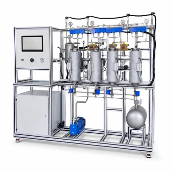
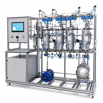
A height-to-diameter (H/D) ratio of at least 3:1 is specified to guarantee that a pilot-scale gas adsorption column behaves like a plug-flow reactor—essential for generating data that scales reliably to industrial equipment. Meeting this geometric minimum confines the mass transfer zone into a sharp, measurable front and suppresses fluid bypassing, channeling, and end effects that would otherwise corrupt breakthrough curves and calculated kinetic parameters. In short, it transforms a laboratory vessel into a representative engineering tool.
The 3:1 H/D ratio exists primarily to suppress axial dispersion and flow maldistribution. When the bed is too short relative to its width, gas can bypass active adsorbent, the mass transfer zone smears out, and exit concentrations no longer reflect true adsorption dynamics. Without this constraint, pilot-plant data lose their predictive power for commercial scale-up.
Why Column Geometry Controls Adsorption Data Quality
The answer goes deeper than “it prevents channeling.” The 3:1 rule is rooted in the physics of fixed-bed adsorption and the statistical requirements of experimental design. Understanding each contributing mechanism reveals why this geometry is non-negotiable for representative results.
Establishing a Sharp, Measurable Mass Transfer Zone
Gas adsorption occurs in a moving front—the mass transfer zone (MTZ) —where the solute transfers from the gas phase onto the solid adsorbent. For clean experimental determination of breakthrough curves, this zone must be confined, narrow, and fully contained within the bed. A column with an H/D ratio below 3:1 often forces the MTZ to occupy a disproportionate fraction of the total bed length, making it impossible to distinguish between equilibrium capacity and rate-limiting kinetics.
A taller, slender column gives the MTZ room to develop and travel without end effects contaminating the measurement. This directly improves the accuracy of derived parameters such as the length of unused bed and the overall mass transfer coefficient.
Eliminating Fluid Bypassing and Channeling
Flow maldistribution is the biggest threat to pilot-plant fidelity. In a short, wide column, gas tends to channel toward the center or follow preferential paths along the wall, bypassing large portions of the adsorbent bed. The result is a broad, tailing breakthrough curve that suggests an erroneously low utilization of the adsorbent.
Maintaining an H/D of at least 3:1 promotes a more uniform velocity profile. When combined with the inert ceramic balls placed in the top and bottom headspace (typically 10–20 % of the column volume), the gas flow redistributes before entering the active bed. This setup mimics the large-scale, near-plug-flow conditions found in industrial adsorbers.
Reducing Entrance and Exit Contamination
Short columns suffer from end effects: the sudden expansion or contraction at the inlet and outlet can create stagnant zones, recirculation, and non-representative mixing. By elongating the column relative to its diameter, the relative volume of these disturbed zones shrinks dramatically. The 3:1 threshold acts as a practical rule-of-thumb that moves disturbances far enough from the measured region that their influence on the overall breakthrough timing becomes negligible.
The Deep Need: Scale-Up Reliability from Day One
Researchers who ignore the H/D constraint often believe their pilot column still “works” because an adsorption front appears. The hidden failure is that their data describe only that specific piece of hardware—not a scalable adsorption process.
Simulating Industrial Plug Flow at the Pilot Scale
Industrial adsorbers operate at large diameters, where wall effects are negligible and flow approaches true plug flow. A pilot column with an H/D of 3:1 or above approximates this hydrodynamic regime by minimizing the ratio of wall surface area to bed cross-section. When the diameter is too large for the given bed height (H/D < 3), radial temperature and concentration gradients develop that are absent in full-scale vessels, creating a mismatch that destructive scale-up decisions.
The Danger of Excessive Axial Dispersion
A low H/D ratio amplifies axial dispersion—the spreading of a tracer front due to molecular diffusion and convective mixing. In such systems, the dimensionless Peclet number becomes too low, and the observed breakthrough curve reflects dispersion more than the true mass transfer resistance. By enforcing a minimum bed length relative to diameter, the H/D rule ensures that convection dominates over backmixing, preserving the step-change nature of the adsorption front.
Understanding the Trade-offs of the 3:1 H/D Rule
The 3:1 minimum is just one link in a chain of interdependent design choices. Applying it blindly can create other problems, so engineers must recognize its limits.
When a Higher Ratio Works—and When It Does Not
Increasing the H/D ratio beyond the minimum sharpens the MTZ further and reduces axial dispersion. However, in small-diameter pilot columns, an extremely high H/D (e.g., >10) can induce wall-channeling effects, where an outsized fraction of the flow travels along the wall instead of through the packed bed. The pressure drop also rises roughly linearly with bed height, which may push the system beyond the allowable blower capacity. The practical sweet spot for most adsorption pilot plants lies between H/D 3 and H/D 8, balancing plug-flow quality against wall artifacts and ΔP.
Distinguishing This Rule from Absorption Column Design
A frequent source of confusion is mixing up rules for gas-liquid absorption with those for gas-solid adsorption. In packed absorption columns, liquid distribution becomes the dominant concern, and individual packed sections are typically limited to 6–10 feet in height to prevent liquid channeling. The H/D constraints there are driven by liquid-to-gas ratio and packing geometry, not by the need to contain a single sharp mass transfer zone. For adsorption pilots, the 3:1 rule targets gas-phase hydrodynamics and MTZ development—a fundamentally different physical constraint that deserves its own, separate guideline.
The Common Mistake of Over-Reliance on Inert Fill
Placing inert ceramic balls above and below the adsorbent bed is an excellent practice to normalize flow, but it cannot compensate for a severely deficient H/D ratio. If the active bed itself is too shallow, even perfectly distributed gas will not create a measurable mass transfer front. Designers sometimes try to “fix” a short column by adding more inert volume; this merely hides the problem behind additional pressure drop and does not produce scale-relevant bed dynamics.
Making the Right Choice for Your Adsorption Pilot Plant
Your specific experimental goal dictates how stringently you must apply the H/D rule and what additional steps to take. Use the following guide to align the column geometry with your research priorities.
- If your primary focus is generating scale-up data for a commercial design: Insist on an H/D of at least 3:1—preferably 5:1—and supplement the inlet section with carefully sized inert distributor balls. This combination most reliably reproduces industrial plug-flow hydrodynamics.
- If your primary focus is isolating intrinsic mass transfer kinetics: Use an H/D ratio >3:1 and keep the column diameter at least 8–10 times the particle diameter to eliminate wall-channeling artifacts. Pre-treat the gas to guarantee a sharp concentration step at the bed inlet.
- If your primary focus is operating with a limited gas supply and minimizing pressure drop: Never compromise below H/D 3:1 to save adsorbent or shorten the column. Instead, reduce the gas flow rate while maintaining the geometry, and accept longer experimental run times as the cost of valid data.
- If your primary focus is teaching fundamentals in a unit operations lab: Use the 3:1 rule to demonstrate why geometry matters, then deliberately run a control experiment with a short, wide column so students can directly observe the break-through curve broadening and loss of efficiency—turning an abstract design rule into a tangible lesson.
The H/D ratio in gas adsorption pilots is not a decorative specification. It is the geometry that turns a bed of particles into a trustworthy instrument—and when it is respected, the data speak the language of full-scale plants.
Summary Table:
| Key Design Aspect | Physical Mechanism | Impact on Scale-Up Data |
|---|---|---|
| MTZ Containment | Confines the mass transfer zone within a sharp front | Ensures accurate determination of breakthrough curves and kinetics |
| Flow Distribution | Suppresses bypassing, channeling, and wall effects | Simulates industrial plug-flow hydrodynamics for representative data |
| End Effects Reduction | Minimizes inlet/outlet disturbances and backmixing | Eliminates data contamination from non-representative mixing |
| Optimal H/D Range (3:1 to 8:1) | Balances uniform flow against wall-channeling and pressure drop | Delivers reliable predictive power for commercial scale-up |
Optimize Your Pilot-Scale Research with LABPARK
Ensure your experimental data translates seamlessly to commercial-scale operations with properly engineered pilot systems. LABPARK design and provides high-quality Educational and Vocational Unit Operations Pilot Plants in chemical engineering, bioprocess & biotech, and environmental & water treatment tailored for universities, research institutes, and enterprises. Our systems are built to precise geometric and hydrodynamic standards—like optimal H/D ratios and advanced flow distribution—to guarantee reliable, scalable results for your research and training needs.
Contact LABPARK today to discuss your custom pilot plant requirements and speak with our engineering experts!
Related Products
- Carbon Dioxide Adsorption and Capture Educational Unit Operations Pilot Plant
- Multi-Component Gas Pressure Swing Adsorption Pilot Plant for Unit Operations Education
- Dual-Mode Gas Absorption and Desorption Unit Operations Training Pilot Plant
- Carbon Dioxide Absorption and Desorption Educational Pilot Plant for Carbon Capture Studies
- Bench Scale Dual Column Gas Separation and Capture Educational Pilot Plant
People Also Ask
- How does operating pressure influence the transition between absorption and desorption in a CO2 pilot plant?
- How is moisture removal managed in an adsorption unit operations pilot plant? Dew Point Control Guide
- How do physical vs chemical adsorption impact pilot plant design? Key operational & regeneration strategies.
- How does slow equilibrium in polymer solutions affect adsorption pilot plants? Key Design & Operating Strategies
- What are the key differences between PSA and TSA? Choosing the Right Adsorption Pilot Plant