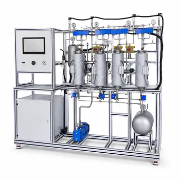
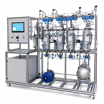
Solvent recycle loops are used to reduce solvent consumption and keep absorber operation stable. In a gas absorption pilot plant, the solvent descends through a packed or trayed column while the gas rises, transferring a soluble contaminant into the liquid phase. The solvent-rich outlet is often regenerated and returned to the absorber, with fresh makeup replacing solvent lost through purge, entrainment, evaporation, or sampling.
The key accounting principle is to distinguish internal recycle flows from external flows. A recycle stream appears in individual unit balances, but it cancels from the overall process balance because it does not cross the outer process boundary.
Why Absorber Pilot Plants Recycle Solvent
Reducing raw material consumption
A recycle loop allows most of the solvent to circulate repeatedly rather than being discarded after one pass through the column.
This is especially important when the solvent is costly, hazardous, or requires treatment before disposal. Pilot plants use recycling to approximate the solvent economy of a larger industrial process.
Maintaining a controlled solvent concentration
Absorption performance depends on the solvent’s composition and flow rate. Returning regenerated solvent helps maintain relatively constant operating conditions in the column.
Without recycling, the solvent composition and inventory would change continuously unless a large fresh-solvent flow were provided. That would make it harder to evaluate column performance consistently.
Supporting solvent regeneration
In many systems, the liquid leaving the absorber contains the captured contaminant. A downstream regeneration step—such as stripping, distillation, or another separation—removes much of the contaminant and produces solvent suitable for return to the absorber.
For example, a solvent may absorb hydrogen sulfide or ammonia in the column and then release it during regeneration. The regenerated liquid becomes the recycle stream.
Improving pilot-scale economics
Pilot plants do not always have the same economies of scale as commercial facilities. Recycling reduces fresh solvent demand, waste generation, and operating cost while allowing extended experiments with a limited solvent inventory.
The loop also provides practical experience with solvent recovery, makeup requirements, impurity accumulation, and steady-state operation.
How to Define the Mass-Balance Boundaries
The absorber boundary
For the absorber alone, define the inlet gas and inlet liquid as entering streams and the treated gas and rich liquid as leaving streams.
A total balance is:
[ G_{\text{in}}+L_{\text{in}}
G_{\text{out}}+L_{\text{out}} ]
where (G) and (L) are gas- and liquid-stream flow rates on a consistent mass or molar basis.
The contaminant balance
For an absorbing species (A), the component balance is:
[ G_{\text{in}}y_{A,\text{in}} + L_{\text{in}}x_{A,\text{in}}
G_{\text{out}}y_{A,\text{out}} + L_{\text{out}}x_{A,\text{out}} ]
Here, (y_A) is the gas-phase fraction of (A), and (x_A) is its liquid-phase fraction. Both must be defined consistently as either mole fractions or mass fractions.
The amount absorbed by the liquid is commonly expressed as:
[ \dot n_{A,\text{absorbed}}
\dot n_{A,\text{gas,in}}
\dot n_{A,\text{gas,out}} ]
when the liquid feed contains negligible (A). If the solvent already contains (A), the liquid inlet term must also be included.
The solvent balance
For a nonreactive solvent (S), the absorber balance is:
[ \dot m_{S,\text{in}}
\dot m_{S,\text{out}} ]
provided there is no solvent evaporation, entrainment, reaction, or other loss within the absorber.
In an actual pilot plant, these losses may be significant enough to require a makeup-solvent stream.
How Recycle Appears in the Process Balance
The mixer balance
Fresh makeup solvent and regenerated recycle solvent combine before entering the absorber:
[ L_{\text{makeup}}+L_{\text{recycle}}
L_{\text{absorber,in}} ]
For solvent component (S):
[ L_{\text{makeup}}x_{S,\text{makeup}} + L_{\text{recycle}}x_{S,\text{recycle}}
L_{\text{absorber,in}}x_{S,\text{in}} ]
This equation determines the flow and composition of the solvent entering the column.
The regeneration balance
The rich liquid leaving the absorber enters the regeneration section. A simplified total balance is:
[ L_{\text{rich}}
L_{\text{regenerated}} + L_{\text{regenerator losses}} + L_{\text{purge}} ]
The corresponding contaminant balance includes the contaminant removed in the regeneration overhead or stripping stream:
[ \dot n_{A,\text{rich}}
\dot n_{A,\text{regenerated}} + \dot n_{A,\text{overhead}} + \dot n_{A,\text{losses}} ]
The exact terms depend on whether the regeneration step is modeled as a stripper, distillation column, flash, or another unit.
The overall process boundary
When the boundary surrounds the absorber, regeneration unit, mixer, and recycle piping, the recycle stream is internal. It enters and leaves the boundary in equal accounting terms and therefore cancels.
The overall steady-state balance is based only on external streams:
[ \text{External inputs}
\text{External outputs} ]
For the contaminant, this generally means:
[ \text{Contaminant in with feed gas} + \text{Contaminant in with makeup}
\text{Contaminant out in treated gas} + \text{Contaminant recovered or purged} + \text{Contaminant in other losses} ]
The contaminant does not simply disappear when it is absorbed. It is transferred from the gas phase to the solvent and must ultimately leave through a regeneration product, purge, waste stream, treated gas, or accumulated inventory.
Why Makeup and Purge Streams Matter
Makeup replaces unavoidable losses
Fresh solvent is added to compensate for solvent leaving the system through liquid purge, gas entrainment, evaporation, equipment drainage, sampling, or regeneration losses.
At steady state, the makeup flow approximately replaces the net solvent loss:
[ L_{\text{makeup}} \approx L_{\text{purge}} + L_{\text{evaporation}} + L_{\text{entrainment}} + L_{\text{other losses}} ]
The equality may require adjustment if solvent enters or leaves through additional process streams.
Purge prevents impurity buildup
A closed solvent loop can accumulate nonvolatile impurities, degradation products, or poorly regenerated contaminants. If none of these materials leaves the system, their inventory increases over time.
A purge removes a controlled fraction of the circulating liquid. Makeup solvent then restores the desired total flow and composition.
Steady state requires no net accumulation
For any component (i), the general balance is:
[ \text{Input}_i-\text{Output}_i
\text{Accumulation}_i ]
At steady state:
[ \text{Accumulation}_i=0 ]
This condition is particularly important for impurities. If the calculated input exceeds output, the loop is not at steady state; the component is accumulating even if the main solvent flow appears constant.
A Practical Balance Sequence
Start with measured flow rates
Measure or estimate gas flow, solvent flow, makeup flow, recycle flow, purge flow, and relevant outlet streams. Use either mass flow rates throughout or molar flow rates throughout.
Mixing mass fractions and mole fractions without conversion is a common source of error.
Balance the absorber
First calculate the contaminant transferred from the gas to the liquid:
[ \dot n_{A,\text{absorbed}}
\dot n_{A,\text{in}}
\dot n_{A,\text{out}} ]
Then compare this value with the increase in contaminant carried by the liquid stream.
Balance the regeneration section
Determine how much absorbed contaminant leaves in the regenerated overhead or product stream and how much remains in the recycle solvent.
The regenerated solvent may still contain some contaminant, so assuming a perfectly pure recycle stream can produce an unrealistic result.
Balance the mixer
Use the makeup and recycle streams to calculate the composition entering the absorber. This step connects solvent-loss calculations with the actual column operating condition.
Check the complete loop
Finally, draw the outer process boundary and remove all internal recycle terms from the overall balance. The external balance should close within the expected measurement uncertainty.
A balance that closes around each unit but fails overall often indicates an omitted purge, unmeasured loss, inconsistent basis, or incorrect stream composition.
Understanding the Trade-offs
Higher recycle reduces solvent use but increases loop complexity
A high recycle rate lowers fresh-solvent demand, but it requires pumps, regeneration equipment, control instrumentation, and additional piping.
It can also increase residence time and make the process more sensitive to gradual impurity accumulation.
Recycle does not guarantee constant solvent quality
The solvent composition depends on regeneration effectiveness, purge rate, contaminant loading, and solvent degradation. Recycling a contaminated stream can gradually reduce absorption capacity.
The recycle stream should therefore be characterized by composition, not only by flow rate.
Purge improves impurity control but wastes useful material
A larger purge removes impurities more effectively, but it also removes solvent and possibly absorbed contaminant that could otherwise be recovered.
The purge rate is therefore a compromise between solvent recovery, impurity control, and operating stability.
Steady-state assumptions may not apply during startup
During startup, shutdown, or a change in operating conditions, solvent and contaminant inventories are changing. The accumulation term cannot be set to zero.
Transient balances are required until the loop reaches a stable operating condition.
Making the Right Choice for Your Goal
Use the balance structure to match the analysis to the question being investigated.
- If your primary focus is solvent consumption: Enclose the entire recycle system and calculate fresh makeup from purge, evaporation, entrainment, and other solvent losses.
- If your primary focus is absorber performance: Balance the absorber separately and compare contaminant entering with contaminant leaving in the gas and liquid streams.
- If your primary focus is solvent quality: Include component balances for the contaminant, solvent, and nonvolatile impurities, along with any purge stream.
- If your primary focus is scale-up: Track both single-pass absorption and overall recovery, recognizing that recycle changes the solvent composition and the effective process operating conditions.
- If your primary focus is data validation: Perform unit-level balances first, then verify that the overall process balance closes after internal recycle streams are canceled.
A recycle loop is best understood not as an additional source or sink, but as an internal circulation path whose benefits and losses become clear through carefully defined component balances.
Summary Table:
| Topic | Key point |
|---|---|
| Solvent recycling | Reduces fresh-solvent consumption and supports stable absorber operation |
| Absorber balance | Accounts for gas and liquid inlet and outlet streams, including contaminant transfer |
| Internal recycle | Appears in individual unit balances but cancels in the overall process balance |
| Makeup solvent | Replaces solvent lost through purge, evaporation, entrainment, drainage, and sampling |
| Purge stream | Controls impurity and degradation-product buildup in the solvent loop |
| Regeneration | Removes absorbed contaminants and returns usable solvent to the absorber |
| Steady-state check | Confirms that each component has zero net accumulation |
| Best practice | Balance individual units first, then verify the complete external-stream balance |
Need a reliable gas absorption pilot plant for teaching, research, or process development? Contact LABPARK to discuss your requirements. LABPARK provides Educational and Vocational Unit Operations Pilot Plants for universities, research institutes, and enterprises, including chemical engineering systems for gas absorption, solvent regeneration, and recycle-loop studies, along with bioprocess and biotech and environmental and water treatment solutions. Our pilot plants help teams evaluate solvent consumption, contaminant removal, makeup and purge requirements, steady-state performance, and scale-up behavior using measurable process data.
Related Products
- Dual-Mode Gas Absorption and Desorption Unit Operations Training Pilot Plant
- Carbon Dioxide Absorption and Desorption Educational Pilot Plant for Carbon Capture Studies
- Carbon Dioxide Adsorption and Capture Educational Unit Operations Pilot Plant
- Absorption and Desorption Educational Unit Operations Pilot Plant
- Packed Bed Absorption Educational Unit Operations Pilot Plant
People Also Ask
- How do temperature and pressure affect gas absorption and desorption? Optimize Pilot Plant Performance
- How do two-film & penetration theories apply to gas absorption pilot plant teaching? Key pedagogical insights.
- How is the direction and driving force of mass transfer determined in a gas absorption unit operations pilot plant?
- How does partial pressure behavior influence gas absorption pilot plants? Master Mass Transfer
- How to model chemical absorption as physical absorption? The pilot plant simplification criterion.