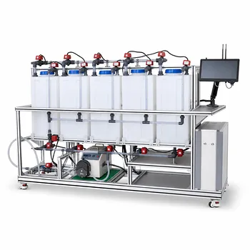
Mitigating concentration polarization and membrane fouling in a pilot plant is fundamentally about controlling what happens at the membrane surface. The core strategies are proactive feed pretreatment, aggressive hydrodynamic optimization, careful selection of operating pressure and temperature, use of fouling-resistant membranes, and a disciplined cleaning schedule. When applied as an integrated protocol, these measures preserve permeate flux, maintain separation accuracy, and generate the reliable data needed to scale up environmental water treatment processes.
The secret to a successful pilot operation is recognizing that concentration polarization and fouling are not inevitable losses—they are manageable boundary-layer and material-science challenges. A systematic strategy that maximizes shear at the membrane, removes foulants before they arrive, and cleans at the right time will keep a pilot plant running predictably and inform a robust full-scale design.
The Root Cause: A Tale of Two Interlinked Problems
Addressing the deep need means first understanding that fouling and polarization feed each other.
The Boundary Layer Problem
Concentration polarization is the buildup of retained solutes in a thin boundary layer right next to the membrane surface. This increase in local concentration raises osmotic pressure, reduces the effective driving force, and can initiate scaling if solubility limits are exceeded. It directly lowers permeate flux and can allow more solute to pass, degrading separation quality.
The Four Faces of Fouling
Membrane fouling goes beyond a simple layer. It classifies into organic fouling (proteins, macromolecules), inorganic scaling (mineral salts), biofouling (microbial growth), and colloidal/particulate fouling. These foulants can adsorb to the surface, block pores, or form a compressible gel. The interactions are both electrostatic and hydrophobic, making them highly dependent on feed water chemistry.
Strategy 1 – Feed Pretreatment: Stop Foulants at the Gate
Removing problematic species before they reach the membrane is the single most effective long-term strategy.
Targeting Specific Contaminants
A proper pretreatment train removes microorganisms, suspended solids, colloids, and soluble organics or scalants. Coagulation and flocculation can aggregate fine particles for removal. Microfiltration or ultrafiltration pre-filters catch larger particulates, while activated carbon adsorption strips out dissolved organic matter that would otherwise feed biofouling or form a gel layer.
pH and Temperature Adjustment
Adjusting the feed pH alters the solubility of inorganic scalants and the charge of organic molecules, reducing their tendency to deposit. Raising the temperature lowers liquid viscosity, which enhances solute diffusion away from the membrane back into the bulk stream—a direct counter to concentration polarization.
Strategy 2 – Hydrodynamic Optimization: Scouring the Membrane Surface
Fluid dynamics are your primary physical weapon against the boundary layer.
Cross-Flow Velocity and Shear
Increasing the cross-flow velocity thins the stagnant boundary layer and boosts the mass transfer coefficient. High shear at the membrane surface sweeps away accumulating solutes and disrupts the formation of a dense gel. Operators control this by adjusting the retentate flow rate and feed pressure.
Turbulence Promoters and Spacers
Even with high bulk velocity, laminar sub-layers can persist. Mesh spacers, corrugated inserts, or engineered baffles inside the membrane module disrupt this laminar flow. They create localized eddies that dramatically enhance back-diffusion of solutes, effectively increasing the limiting flux without requiring a proportional increase in pump energy.
Multi-Stage Recirculation Design
In a pilot plant, experimenting with multi-stage configurations and brine recirculation can maintain high recovery rates (e.g., 96–98% salt rejection in RO) while preventing any single module from exceeding the local saturation concentration. This design strategy keeps solute concentrations manageable across the entire system.
Strategy 3 – Operating Parameter Control: Staying Below Critical Limits
The membrane system has a “safe operating window” beyond which fouling accelerates catastrophically.
Pressure vs. Gel Layer Formation
While higher transmembrane pressure initially increases flux, it also compresses the boundary layer and can compact a gel layer into a dense, high-resistance film. Selecting an operating pressure that balances flux with a manageable gel-layer density is critical. The goal is to operate just below the point of rapid flux decline.
Temperature and Diffusion
Operating at a moderately elevated feed temperature lowers viscosity and increases the solute diffusion coefficient. This accelerates the natural back-diffusion that counteracts concentration polarization. However, the temperature must stay within the membrane’s chemical tolerance and not promote biological growth.
Current Density in Electrodialysis
For electrodialysis pilots, concentration polarization manifests as ion depletion, leading to water splitting and energy loss. The proven mitigation is to run the stack at approximately 80% of the limiting current density ($i \approx 0.8 i_{lim}$). Coupled with higher flow rates and thinner membrane stacks, this maintains efficient separation.
Strategy 4 – Membrane Selection and Modification
Not all membranes are created equal; the surface chemistry dictates the initial fouling rate.
Matching Material to Feed Chemistry
Hydrophilic, smooth, or charge-modified membrane surfaces resist organic and colloidal adsorption. In a pilot plant, testing membranes with grafted anti-fouling layers or low-protein-binding properties can significantly extend the time between cleanings. The right material choice is a passive, always-on defense that works in concert with hydrodynamic strategies.
Strategy 5 – Cleaning Protocols: Restoring Performance
Even the best prevention strategies will eventually need a reset.
Physical vs. Chemical Cleaning
Periodic physical cleaning, such as high-velocity flushing, backwashing, or air sparging, dislodges loose foulants. When flux does not recover, a chemical cleaning-in-place (CIP) protocol must follow. Acids dissolve inorganic scales, bases remove organic films, surfactants displace hydrophobic foulants, and enzymes specifically break down targeted organic deposits without damaging the polymer matrix.
Real-Time Monitoring for Smart Cleaning
Fouling indicators—like pressure drop across the module, decline in permeate flux, and changes in conductivity—act as vital signs. Integrating sensors allows the control system to trigger cleaning cycles based on actual need, not just a fixed calendar. This prevents both unnecessary downtime and operation with severely compromised membranes.
Understanding the Trade-offs
Every mitigation strategy carries a cost, and ignoring them leads to pilot-plant failures.
The Energy vs. Flux Balance
Higher cross-flow velocities and turbulence promoters reduce fouling but demand significantly more pump energy. Pushing from laminar to turbulent flow regimes increases pressure drop and operating cost. The pilot plant must optimize for the lowest total cost of ownership, not just the highest flux.
Cleaning Aggressiveness vs. Membrane Life
Harsh chemical cleaning agents, especially those at extreme pH or with strong oxidants, can degrade the membrane’s active layer over time. A pilot program that cleans too aggressively will produce unrepresentatively short membrane lifetimes and risk sudden failure. The cleaning strategy must be strong enough to restore flux but gentle enough to preserve long-term material integrity.
Capital Cost vs. Operational Simplicity
Adding extensive multi-media pretreatment, advanced spacers, and automated monitoring increases upfront capital and complexity. A simple system might foul faster but be easier for operators to manage. The right choice depends on whether the pilot’s goal is to test a highly resilient industrial design or to demonstrate a low-cost, low-maintenance process.
Making the Right Choice for Your Pilot Plant
Your specific mitigation strategy must align with the operational goals of the environmental water treatment study.
- If your primary focus is maximizing sustained flux for high-throughput testing: Prioritize high cross-flow velocity, turbulence promoters, and frequent physical backwashing, and select an inherently hydrophilic membrane.
- If your primary focus is understanding long-term fouling behavior under realistic conditions: Run at moderate flux and pressure, implement a controlled pretreatment train that mimics the full-scale design, and use timed chemical CIP cycles while logging pressure drop to map fouling rates.
- If your primary focus is energy efficiency and low carbon footprint: Operate at lower pressures with a temperature that provides a diffusion benefit without extra heating, and invest in real-time sensors to clean only when needed, avoiding unnecessary pump work.
- If your primary focus is testing different feed water chemistries or seasonal variations: Use a flexible pretreatment skid with pH control and interchangeable pre-filters, and select membrane materials that are resistant to the widest range of foulants first, then optimize.
A membrane pilot plant does not simply observe fouling—it actively engineers the boundary layer. By combining strategic fluid dynamics, chemical foresight, and materials science, you transform the pilot from a fouling experiment into a reliable platform that delivers the true performance data needed for full-scale environmental water treatment.
Summary Table:
| Strategy | Mechanism | Key Actions | Trade-off |
|---|---|---|---|
| Feed Pretreatment | Removes foulants before the membrane | Coagulation, MF/UF pre-filtration, pH control | Higher capital cost |
| Hydrodynamic Optimization | Increases shear and back-diffusion | High cross-flow velocity, turbulence spacers | Higher pumping energy |
| Parameter Control | Keeps system below critical fouling limits | Optimize transmembrane pressure & temperature | Lower initial operating flux |
| Membrane Selection | Minimizes solute surface adhesion | Use hydrophilic, smooth, or modified membranes | Higher material costs |
| Cleaning Protocols | Restores degraded flux performance | Physical backwashing, chemical CIP cycles | Potential membrane wear |
Optimize Your Water Treatment Research with LABPARK
Are you looking to scale up your environmental processes or train the next generation of engineers? LABPARK provides advanced Educational and Vocational Unit Operations Pilot Plants in chemical engineering, bioprocess & biotech, and environmental & water treatment designed specifically for universities, research institutes, and enterprises.
Our pilot plants are engineered to help you study membrane behavior, optimize hydrodynamics, and develop effective fouling mitigation strategies under realistic conditions.
Contact our team today to discuss your laboratory configuration and custom pilot plant requirements.
Related Products
- Photocatalytic Membrane Separation and Degradation Unit Operations Pilot Plant
- Ultrafiltration Membrane Separation Educational Pilot Plant
- Multifunctional Membrane Separation Educational Pilot Plant with Ultrafiltration, Nanofiltration, Reverse Osmosis
- Hollow Fiber Ultrafiltration Membrane Separation Educational Pilot Plant
- Multi-Functional Membrane Separation Educational Pilot Plant for Unit Operations Lab
People Also Ask
- What are the key differences in membrane configurations? Choose the Right Unit Operations Pilot Plant
- How do polymer membranes restrict gas separation? Key pilot plant limits.
- How do temperature and pH affect membrane conductivity? Pilot Plant Guide
- How Do Pervaporation, Vapor, and Gas Permeation Differ in Pilot Plants? Key Comparison
- How do membrane separation pilot plants teach RO limits? Master osmotic pressure dynamics.