The symmetry condition (\tau_{xy}=\tau_{yx}) simplifies shear analysis by reducing the stress tensor to six independent components and enforcing mechanical consistency. In pilot-scale mixers and filtration systems, this lets engineers determine wall and surface forces from the local stress field without treating each directional shear component as unrelated. The result is more reliable prediction of shear exposure, torque, pressure loss, membrane loading, and equipment-scale flow behavior.
Core takeaway: Stress-tensor symmetry is a consequence of angular-momentum conservation when internal body couples are absent. It reduces the number of independent stresses, simplifies force and torque calculations, and provides a consistent basis for analyzing shear in stirred tanks, membrane modules, and fluid-friction equipment.
Why the Stress Tensor Is Symmetric
The stress tensor contains directional force information
The Cauchy stress tensor can be written as
[ \boldsymbol{\tau}= \begin{bmatrix} \tau_{xx} & \tau_{xy} & \tau_{xz}\ \tau_{yx} & \tau_{yy} & \tau_{yz}\ \tau_{zx} & \tau_{zy} & \tau_{zz} \end{bmatrix}. ]
The diagonal terms represent normal stresses, while the off-diagonal terms represent shear stresses acting on differently oriented surfaces.
Symmetry follows from angular-momentum conservation
For an ordinary fluid without internal volumetric torques or couple stresses, conservation of angular momentum requires
[ \tau_{xy}=\tau_{yx}, \qquad \tau_{xz}=\tau_{zx}, \qquad \tau_{yz}=\tau_{zy}. ]
This does not mean the shear stress is identical everywhere in the equipment. It means that corresponding stress components at the same point must be equal when the surface and force directions are interchanged.
The number of unknowns is reduced
A general three-dimensional stress tensor has nine components. Symmetry reduces this to six independent components: three normal stresses and three shear stresses.
That reduction matters in computational models and experimental interpretation because fewer independent quantities must be calculated, measured, or validated.
How Symmetry Helps Analyze Shear Forces
It defines the traction on any surface consistently
The force per unit area acting on a surface with unit normal (\mathbf{n}) is the traction vector
[ \mathbf{t}=\boldsymbol{\tau}\mathbf{n}. ]
Once the six independent stress components are known, the complete force vector on any oriented surface can be determined. This includes vessel walls, impeller blades, filter membranes, and internal supports.
It prevents inconsistent force and torque predictions
If (\tau_{xy}) and (\tau_{yx}) were independent in an ordinary fluid, the stress field could generate an unbalanced local torque. The symmetry condition removes that nonphysical possibility.
For pilot-scale equipment, this provides a mechanically consistent basis for calculating forces on rotating impellers, shear loads on membranes, and stresses transmitted to vessel walls.
It simplifies numerical simulations
In CFD or finite-element formulations, the solver can represent the stress field using six independent values rather than nine. This reduces the number of constitutive quantities that must be evaluated and provides a useful check: a calculated stress tensor that is materially nonsymmetric may indicate a modeling, discretization, or implementation problem.
Symmetry alone does not determine the stress values. A constitutive relationship—such as a Newtonian or non-Newtonian viscosity model—is still required.
Application to Pilot-Scale Mixing Equipment
Stirred-tank shear can be resolved from the local stress field
In a stirred tank, velocity gradients are strong near impeller blades, baffles, vessel walls, and gas–liquid interfaces. For a Newtonian fluid, the viscous stress is related to the rate-of-deformation tensor, commonly expressed as
[ \tau_{ij}=2\mu D_{ij}, ]
where (\mu) is dynamic viscosity and (D_{ij}) is the symmetric part of the velocity-gradient tensor.
The stress symmetry is therefore consistent with the fact that viscous stress responds to fluid deformation rather than to an arbitrary choice of coordinate direction.
It supports microorganism shear-exposure estimates
Bioreactor designers often need to identify regions where cells may experience damaging levels of shear. The local stress tensor can be used to estimate wall shear stress, stress magnitude, and high-shear zones around impellers and other geometric restrictions.
This is more informative than relying only on bulk agitation speed or average power input, because shear is spatially nonuniform.
It assists impeller and vessel design
The stress field contributes to the forces and torques acting on impellers. Integrating the traction over blade surfaces gives the net force, while the moment of traction gives the torque required for agitation.
These calculations support decisions involving mixing uniformity, motor sizing, impeller geometry, and energy-efficient agitation.
Application to Pilot-Scale Filtration Equipment
Membrane loading includes both normal and tangential stresses
In a membrane module, the pressure-driven component acts normal to the membrane, while crossflow produces tangential shear. The stress tensor provides a unified way to evaluate both effects at the membrane surface.
The tangential traction is particularly relevant to boundary-layer development, concentration polarization, and the removal or suppression of deposited material.
It helps evaluate wall shear and fouling conditions
Local wall shear stress can vary substantially near spacers, channel entrances, bends, and module outlets. Using the complete stress tensor allows engineers to calculate the traction on the actual membrane orientation rather than approximating shear from a single velocity component.
This supports comparisons between module geometries and operating conditions during pilot testing.
It supports scale-up interpretation
Pilot filtration equipment is often used to determine whether laboratory observations persist at larger flow rates and channel dimensions. Stress-tensor analysis helps distinguish the effects of bulk flow, local wall shear, pressure distribution, and geometry.
The symmetry condition ensures that these calculations remain consistent when the coordinate system or surface orientation changes.
The Role of Velocity Gradients and Viscosity
Symmetry reduces the stress description, but does not replace a fluid model
For a Newtonian fluid, shear stresses can be calculated from viscosity and the symmetric velocity-gradient tensor. For non-Newtonian fluids, the relationship may involve shear-dependent viscosity, yield behavior, viscoelasticity, or other constitutive effects.
Therefore, the statement that stresses can be calculated from velocity gradients and viscosity is valid only when the selected constitutive model appropriately describes the fluid.
Coordinate orientation still matters
The individual values of (\tau_{xy}), (\tau_{xz}), and related components depend on the chosen coordinate system. The physical traction on a real surface is obtained by applying the stress tensor to that surface’s normal vector.
This is important in equipment with curved walls, rotating components, angled membranes, and complex internal structures.
Understanding the Trade-offs
Symmetry does not eliminate three-dimensional complexity
Reducing nine components to six independent components simplifies the mathematics, but pilot equipment may still have strongly three-dimensional, transient, and multiphase flow.
Gas dispersion, particle suspension, free surfaces, membrane spacers, and recirculation zones can make local shear difficult to predict even when the stress tensor is symmetric.
Average shear values can hide damaging local peaks
Using a vessel-average shear rate or average membrane crossflow may conceal high-stress regions near impeller tips, narrow clearances, baffles, or spacer filaments.
A reliable assessment should examine local stress distributions and, where relevant, time-dependent exposure rather than only bulk averages.
Specialized materials require caution
The ordinary symmetric Cauchy stress assumption applies to conventional continua without couple stresses. Materials with micropolar behavior, strong internal rotational structure, or explicitly modeled couple stresses may require a generalized theory in which additional moment stresses are present.
Such cases are uncommon in standard pilot-scale mixing and filtration analysis but should not be ruled out automatically for unusual suspensions or structured fluids.
How to Apply This to Your Project
Symmetry is most useful when it is combined with an appropriate constitutive model, accurate geometry, and local rather than purely average flow analysis.
- If your primary focus is bioreactor shear exposure: Use the symmetric stress tensor and local velocity gradients to identify high-shear regions around impellers, baffles, and walls, then relate those regions to microorganism sensitivity.
- If your primary focus is impeller or motor design: Integrate the stress-derived traction over impeller surfaces to estimate net forces and agitation torque.
- If your primary focus is membrane filtration: Resolve the traction on the membrane surface into normal and tangential components to assess pressure loading, wall shear, and fouling-control conditions.
- If your primary focus is CFD validation: Check that the computed stress tensor is symmetric for an ordinary fluid and verify that the constitutive model matches the fluid’s Newtonian or non-Newtonian behavior.
- If your primary focus is scale-up: Compare local stress distributions, residence-time exposure, and boundary-layer behavior rather than relying only on matched bulk flow rate or average power input.
Understanding stress-tensor symmetry gives you a simpler, mechanically consistent foundation for turning complex pilot-scale flow fields into actionable shear-force and equipment-design information.
Summary Table:
| Application | What symmetry enables | Key design insight |
|---|---|---|
| Stirred tanks | Consistent traction, force, and torque calculations | Identify local high-shear zones and size impellers or motors |
| Bioreactors | Local stress and shear-exposure estimates | Protect sensitive microorganisms during scale-up |
| Membrane filtration | Resolve normal pressure and tangential wall shear | Evaluate fouling, membrane loading, and crossflow effects |
| CFD and validation | Reduce nine stress components to six independent values | Check model consistency and constitutive behavior |
| Scale-up studies | Compare local stress distributions and boundary layers | Avoid relying only on average flow rate or shear values |
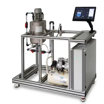
Planning a pilot-scale mixing, bioprocess, or filtration project? Contact LABPARK for expert support selecting and applying Educational and Vocational Unit Operations Pilot Plants. Our chemical engineering, bioprocess and biotech, and environmental and water treatment systems help universities, research institutes, and enterprises evaluate local shear, impeller torque, membrane loading, pressure loss, fouling conditions, and scale-up performance. LABPARK can help you choose practical pilot-plant configurations, match equipment to your fluid and process objectives, and turn reliable flow data into better teaching, research, process development, and equipment decisions.
Related Products
- Agitation and Mixing Educational Unit Operations Pilot Plant
- Hot Filtration Educational Unit Operations Pilot Plant Laboratory System
- Ultrafiltration Membrane Separation Educational Pilot Plant
- Constant Pressure Filtration Educational Unit Operations Pilot Plant
- Multifunctional Membrane Separation Educational Pilot Plant with Ultrafiltration, Nanofiltration, Reverse Osmosis
People Also Ask
- Why is the Reynolds number ($Re_M$) critical in mixing? Master N_P for pilot plants.
- What are the four guiding principles of process intensification? Educational Equipment Guide
- How do educational unit operations pilot plants support process analysis? Connect theory with real data
- How does the pseudobinary diffusion approximation simplify mass transport equations in educational pilot plants?
- Why is post-implementation performance evaluation and gap analysis critical when deploying educational unit operations pilot plants?