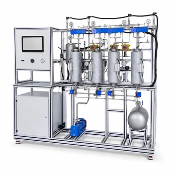
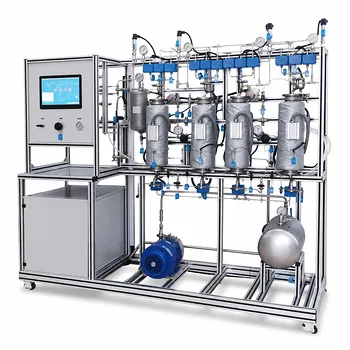
The ability to design an effective gas absorption column hinges on Dalton’s Law of Partial Pressures because it directly defines the driving force that moves pollutants from the gas phase into the liquid solvent. In a scrubbing column, the rate at which a target gas (like CO₂ or H₂S) transfers into the liquid is proportional to the difference between its partial pressure in the bulk gas and its equilibrium partial pressure at the liquid interface. Without accurately applying Dalton’s Law to calculate these partial pressures under real operating conditions, you cannot determine the column height required, the solvent flow needed, or the overall removal efficiency—making it the very first calculation for any successful pilot-scale gas absorption unit.
While Dalton’s Law may seem like a simple arithmetic relationship, it is the heartbeat of gas absorption design: the difference in partial pressure is the engine of mass transfer, and every design parameter—from column height to solvent regeneration—flows directly from how well you quantify that difference.
The Mass Transfer Engine: Partial Pressure Difference
The Driving Force for Gas Absorption
Mass transfer in a scrubbing column occurs because a component moves from a region of high partial pressure to one of low partial pressure. In the absorber, the solute’s partial pressure in the bulk gas phase is higher than its equilibrium partial pressure at the gas‑liquid interface. That difference is the driving force—the steeper the gradient, the faster the absorption rate.
Partial Pressure and Equilibrium
Dalton’s Law gives you the solute’s partial pressure as ( p_i = P_{\text{total}} \times y_i ). The liquid side’s equilibrium partial pressure is then determined by thermodynamic models (Henry’s Law, Edwards’ correlation, or Pitzer equations). By linking gas composition, total pressure, and equilibrium data, you can predict the maximum possible removal and set the lower bound for the driving force.
From Partial Pressure to Column Height: HTU and NTU
How HTU Depends on Driving Force
The height of a transfer unit (HTU) is inversely related to the mass‑transfer coefficient, which itself depends on the average driving force across the column. A smaller partial pressure difference increases the required column height. Miscalculating that difference—by ignoring Dalton’s Law—leads directly to an oversized or underperforming pilot unit.
Calculating Minimum Solvent Flow
On a McCabe‑Thiele diagram, the equilibrium line is constructed from equilibrium partial pressure data. The operating line’s slope depends on the liquid‑to‑gas ratio. Using Dalton’s Law to fix the endpoints (inlet and outlet partial pressures) lets you calculate the minimum solvent flow rate and the number of transfer units (NTU) needed to meet emission targets—essentially the complete design basis for the column.
The Impact of Operating Conditions in a Pilot Plant
Temperature Swings Change the Driving Force
In a pilot plant, temperatures can fluctuate due to reaction heat or ambient changes. A higher temperature raises the solute’s equilibrium partial pressure over the solvent, shrinking the driving force. Without temperature‑corrected partial pressures (a direct application of Dalton’s Law), you will misinterpret a drop in efficiency as a column fault rather than a normal thermodynamic shift.
Total Pressure as a Design Lever
Raising total pressure increases the solute’s partial pressure proportionally. This is one of the most powerful levers to boost absorption capacity and reduce column height. Dalton’s Law quantifies this leverage precisely—without it, you are only guessing the effect of a pressure increase on removal efficiency.
Understanding the Limitations and Common Pitfalls
When Ideal Gas Behavior Isn’t Enough
Dalton’s Law assumes ideal gas behavior. At high pressures (above roughly 10 bar) or with polar species, fugacity corrections become necessary. Ignoring non‑ideality can underestimate the actual driving force and lead to a dangerously oversized or over‑costed column at the full‑scale plant.
The Hidden Feedback Loop of Solvent Regeneration
In a closed‑loop absorption‑desorption pilot plant, the equilibrium partial pressure of the regenerated lean solvent sets the starting point for the next absorption cycle. If regeneration is incomplete, even a small residual solute concentration in the solvent raises its equilibrium partial pressure, catastrophically collapsing the driving force. Operators who fail to monitor and model this with Dalton’s Law will see efficiency drop without an obvious cause.
Applying Dalton’s Law for Pilot‑Plant Success
To turn this principle into better results, align your partial‑pressure calculations with your specific goal.
- If your primary focus is maximizing removal efficiency: Continuously measure gas composition and temperature at inlet and outlet. Use Dalton’s Law to calculate the real‑time driving force, and adjust solvent flow or column pressure to maintain the desired partial pressure gradient.
- If your primary focus is scale‑up from pilot data: Validate your HTU/NTU model against pilot runs using accurate partial pressure profiles. Include fugacity corrections if the operating pressure is high, to avoid undersizing the commercial column.
- If your primary focus is cost reduction through solvent regeneration: Track the equilibrium partial pressure of the regenerated solvent stringently. A small rise in residual solute directly cuts the driving force, forcing higher circulation rates and energy consumption—an operational decision made precise through Dalton’s Law.
By making Dalton’s Law the cornerstone of your pilot plant’s data analysis, you transform a simple gas law into a powerful tool for designing cleaner, more efficient environmental processes.
Summary Table:
| Key Parameter | Role of Dalton's Law | Operational Impact |
|---|---|---|
| Driving Force | Defines the gas-liquid concentration gradient | Determines pollutant removal rate |
| Column Height | Calculates HTU/NTU based on partial pressure | Prevents undersizing or oversizing |
| Solvent Flow | Establishes the equilibrium operating line | Minimizes solvent use & energy costs |
| Process Variables | Models temperature/total pressure changes | Guides real-time control adjustments |
Optimize Your Environmental Unit Operations with LABPARK
Are you looking to equip your laboratory or training center with reliable, high-performance pilot units? LABPARK provides premium Educational and Vocational Unit Operations Pilot Plants in chemical engineering, bioprocess & biotech, and environmental & water treatment for universities, research institutes, and enterprises.
Our systems—including state-of-the-art gas absorption and scrubbing columns—are engineered to help you accurately model thermodynamic principles like Dalton's Law for seamless scale-up and hands-on learning.
Contact LABPARK experts today to discuss your pilot plant requirements and get a tailored solution!
Related Products
- Packed Bed Absorption Educational Unit Operations Pilot Plant
- Absorption and Desorption Educational Unit Operations Pilot Plant
- Bench Scale Dual Column Gas Separation and Capture Educational Pilot Plant
- Pressure Swing Adsorption Educational Unit Operations Pilot Plant
- Multimodal Absorption and Desorption Pilot Plant for Unit Operations Training
People Also Ask
- How Do Flow Regimes Transition in Packed Bed Pilot Plants? Key Scale-up Insights
- How does reactant concentration determine absorption column control? Gas-film vs. dual-film.
- How is the packing height of an absorption column calculated? Master HTU & NTU Concepts
- How does the wall effect impact packed-bed conversion? Essential pilot plant scale-up tips.
- How does static vs. operating holdup affect pilot plant calibration? Avoid Critical Scale-Up Errors