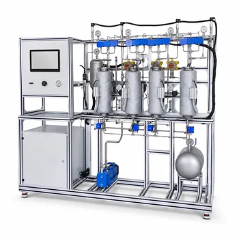
Gas separation and condensation pilot plants make phase-change separation visible, measurable, and designable. They cool or compress a multicomponent gas until one or more components reach condensation conditions, then use vessel geometry and controlled flow to remove the liquid from the remaining gas. In this way, engineers can connect boiling-point differences and vapor–liquid equilibrium to practical decisions about temperature, pressure, residence time, equipment sizing, and product recovery.
Core takeaway: A condensation pilot plant demonstrates that separation occurs when operating conditions move a mixture across its vapor–liquid equilibrium boundary. The condensed, higher-boiling material leaves through the liquid outlet, while the non-condensed gas exits separately; sensors and material balances reveal how effectively the process performs.
How Pilot Plants Demonstrate Phase-Change Separation
Cooling creates a selective phase change
A gas mixture contains components with different volatilities. When the stream is cooled, the less volatile or higher-boiling component reaches its saturation condition first and begins forming liquid.
For example, in ammonia synthesis, ammonia has a normal boiling point near −33°C, while nitrogen and hydrogen boil at approximately −196°C and −253°C, respectively. Cooling the reactor effluent can therefore condense ammonia while most nitrogen and hydrogen remain gaseous.
The separation is not caused by temperature alone. Pressure, composition, and vapor–liquid equilibrium determine the actual condensation temperature and the amount recovered.
The condenser creates two outlet phases
A typical pilot plant sends the process gas through a heat exchanger or condenser. Heat is removed until the target component partially or substantially changes from vapor to liquid.
The two-phase stream then enters a separator vessel. Because of gravity and density differences, the liquid collects at the bottom and exits through a liquid outlet, while the lighter residual gas leaves from the top.
This arrangement allows students and engineers to observe the physical meaning of a standard process flowsheet: heat removal produces the phase change, and the downstream vessel completes phase disengagement.
Gas separation can involve more than condensation
Not every gas-separation operation is a phase-change separation. Absorption, adsorption, membrane separation, and chemical reaction use different mechanisms.
However, gas-processing pilot plants often combine these operations. For example, a wet natural-gas system may use absorption for acid-gas removal, dehydration for water control, and condensation or distillation to recover heavier hydrocarbons.
This distinction matters in process design because each mechanism requires different equilibrium data, equipment, controls, and operating limits.
What the Pilot Plant Teaches About Process Design
Temperature is a primary design variable
Pilot plants demonstrate how condenser temperature affects recovery and product purity.
If the temperature is too high, insufficient target material condenses and valuable product remains in the gas. If it is too low, additional components may condense, reducing selectivity and increasing refrigeration demand.
The practical design task is therefore not simply to maximize cooling. It is to select a temperature that achieves the required recovery, purity, and energy performance.
Pressure changes condensation behavior
Compression increases the partial pressure of a condensable component and can make condensation possible at a higher, more manageable temperature.
This principle is used in solvent-recovery systems. A gas stream carrying solvent vapor may be compressed and then cooled below the solvent’s saturation dew point, causing the solvent to condense while the inert carrier gas remains largely gaseous.
The pilot plant allows operators to vary pressure and observe how the dew point, liquid recovery, and residual vapor concentration change.
Flow arrangement affects heat transfer
The condenser must remove enough heat from the gas stream to reach the intended equilibrium condition. Its performance depends on heat-transfer area, temperature difference, flow rate, fouling, and the physical properties of the process stream.
Pilot-scale equipment demonstrates that thermodynamic feasibility does not automatically guarantee practical separation. A component may be capable of condensing, but inadequate heat-transfer area or residence time can limit the actual recovery.
Vessel geometry supports phase disengagement
After condensation, the liquid and gas must separate hydraulically. The separator requires sufficient volume and residence time for droplets to settle and for entrained gas bubbles to disengage.
Pilot plants make these effects visible through glass sections, level indicators, and interface monitoring. They show why liquid carryover into the gas outlet and gas entrainment in the liquid outlet are important design concerns.
The Role of Equilibrium and Material Balances
Vapor–liquid equilibrium provides the design basis
Vapor–liquid equilibrium, or VLE, describes how each component distributes between the vapor and liquid phases at a specified temperature, pressure, and composition.
For multicomponent systems, the component with the highest boiling point is not necessarily the only component that condenses. Several components may enter the liquid phase, particularly as the temperature decreases or the pressure increases.
Pilot plants provide data for comparing measured outlet compositions with equilibrium predictions and for identifying whether the condenser is operating near the intended design condition.
Partial pressure controls vapor saturation
A condensable component begins to form liquid when its partial pressure reaches the relevant saturation pressure at the operating temperature.
This is especially important for dilute solvent vapor in an inert gas. The total pressure may be high, but condensation depends on the solvent’s partial pressure and its saturation behavior.
Consequently, gas composition measurements are as important as temperature and pressure measurements when evaluating a condensation unit.
Balances quantify performance
A pilot plant supports component-level material balances around the condenser and separator:
- Feed component flow
- Liquid product flow
- Residual vapor flow
- Condensed fraction
- Unaccounted losses or measurement error
Energy balances can also determine the required cooling duty and assess whether the process is consistent with the measured phase change.
These calculations transform a visual demonstration into a process-design method.
How Integrated Pilot Plants Extend the Demonstration
Condensation can be linked to reaction systems
In a synthesis pilot plant, a reactor may produce a gas mixture that flows directly to a condenser and phase separator.
The reactor demonstrates chemical conversion, while the condenser demonstrates physical recovery of a product. This arrangement helps separate the roles of reaction kinetics, heat transfer, equilibrium, and downstream purification.
An ammonia-type system is a clear example: ammonia is produced in the reactor and selectively condensed from the recycle gas after cooling.
Distillation demonstrates repeated phase change
A single condenser provides one equilibrium-based separation step. A distillation column repeats vaporization and condensation across multiple stages, producing stronger separation between components.
Pilot columns allow users to study temperature profiles, reflux, pressure effects, stage efficiency, and product composition. They extend the basic condenser principle into a complete multicomponent purification process.
Vaporization prepares feeds for gas-phase processing
Integrated systems may also include a vaporizer before a catalytic reactor. The vaporizer converts liquid intermediates into a controlled gas-phase feed, while a downstream condenser reverses the phase change for product recovery.
This sequence demonstrates that phase change is not only a separation tool. It is also a way to control reaction-phase conditions and connect otherwise incompatible unit operations.
Auxiliary units reveal complete process interactions
Industrial gas-processing pilot plants may combine condensers with absorbers, dehydration units, separators, and distillation columns.
For example, a wet natural-gas process can remove acid gases by absorption, water by dehydration, and heavier hydrocarbons by condensation or fractional distillation. The integrated pilot plant shows how one unit’s outlet conditions become the next unit’s feed conditions.
Understanding the Trade-offs
Higher recovery can reduce selectivity
More aggressive cooling generally increases condensation of the target component, but it may also condense unwanted components.
The design must balance recovery against product purity, refrigeration duty, and the need for additional downstream separation.
Compression improves recovery but consumes energy
Increasing pressure can raise condensable partial pressures and reduce the refrigeration load required for a given recovery.
Compression, however, requires capital, power, cooling, and mechanical safeguards. The best design is determined by the complete process energy balance rather than by condensation performance alone.
Equilibrium does not guarantee complete separation
A pilot plant may approach equilibrium without achieving perfect separation. Finite residence time, poor mixing, droplet entrainment, heat-transfer limitations, pressure drop, and measurement uncertainty can all reduce performance.
Scale-up must therefore include both thermodynamics and transport phenomena.
Condensation may create operating hazards
Low-temperature equipment can cause material embrittlement, freezing, blocked lines, and hazardous pressure buildup. Reactive, toxic, or flammable gases require appropriate containment, relief systems, ventilation, and instrumentation.
Educational plants commonly use transparent sections and safer model fluids where direct observation is valuable but industrial conditions would present excessive risk.
Making the Right Choice for Your Goal
A pilot plant should be evaluated as both a separation device and a controlled experiment.
- If your primary focus is demonstrating phase equilibrium: Use a condenser and separator with adjustable temperature and pressure, composition analysis, and visible liquid–gas interfaces.
- If your primary focus is maximizing product recovery: Combine compression, staged cooling, liquid drainage, and recycle while measuring residual condensable vapor in the gas outlet.
- If your primary focus is product purity: Use condensation as a first recovery step and follow it with distillation or another selective separation process.
- If your primary focus is industrial process design: Integrate reactors, heat exchangers, separators, absorbers, and distillation equipment so that complete material and energy balances can be tested.
- If your primary focus is scale-up: Measure heat-transfer performance, pressure drop, residence time, droplet carryover, and separation efficiency rather than relying only on equilibrium predictions.
By connecting phase equilibrium to real equipment behavior, gas separation and condensation pilot plants turn an abstract thermodynamic principle into an actionable process-design understanding.
Summary Table:
| Design factor | What the pilot plant demonstrates | Main trade-off or consideration |
|---|---|---|
| Temperature | Controls selective condensation, recovery, and product purity | Excessive cooling may condense unwanted components and increase energy use |
| Pressure | Changes partial pressure, dew point, and condensation behavior | Compression can improve recovery but increases power and safety requirements |
| Heat transfer | Determines whether the stream reaches the intended equilibrium condition | Area, fouling, flow rate, and temperature difference affect performance |
| Phase separation | Uses vessel geometry and residence time to disengage liquid from gas | Poor design can cause liquid carryover or gas entrainment |
| VLE and composition | Predicts component distribution between vapor and liquid phases | Equilibrium data and composition measurements are required for reliable design |
| Material and energy balances | Quantifies condensed fraction, recovery, cooling duty, and losses | Measurement uncertainty can affect scale-up decisions |
| Process integration | Connects reactors, condensers, separators, absorbers, vaporizers, and distillation | Complete designs must balance thermodynamics, transport, energy, and safety |
| Scale-up testing | Measures heat-transfer performance, pressure drop, residence time, and separation efficiency | Equilibrium alone does not guarantee industrial performance |
Apply Phase-Change Principles to Your Process
Turn thermodynamic theory into measurable process-design results with LABPARK Educational and Vocational Unit Operations Pilot Plants. Our configurable systems help universities, research institutes, and enterprises study gas separation, condensation, vaporization, distillation, absorption, heat transfer, phase equilibrium, and complete material and energy balances.
Whether you need a visible teaching system for chemical engineering courses, a research platform for testing operating conditions, or an integrated pilot plant for process development and scale-up, LABPARK can help you evaluate temperature, pressure, recovery, purity, heat-transfer performance, phase disengagement, and safety requirements with practical equipment and instrumentation.
Contact LABPARK to discuss your application and select the right pilot plant for your target process, teaching objectives, research program, or industrial development needs.
Related Products
- Multi-Component Gas Pressure Swing Adsorption Pilot Plant for Unit Operations Education
- Gas-Solid Heterogeneous Separation Demonstration Educational Unit Operations Pilot Plant
- Bench Scale Dual Column Gas Separation and Capture Educational Pilot Plant
- Educational Pressure Swing Adsorption Ethylene Capture Unit Operations Pilot Plant
- Pressure Swing Adsorption Educational Unit Operations Pilot Plant
People Also Ask
- How does Pressure Swing Adsorption (PSA) technology operate? Optimize gas separation with pilot plants.
- How do two-film & penetration theories apply to gas absorption pilot plant teaching? Key pedagogical insights.
- How is the direction and driving force of mass transfer determined in a gas absorption unit operations pilot plant?
- How does partial pressure behavior influence gas absorption pilot plants? Master Mass Transfer
- What are the limitations of Henry's Law in gas absorption pilot plants? Avoid critical lab errors.