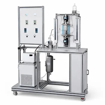
The pressure drop you measure across the acceleration tube is a direct bill for moving your particles. The total pressure drop in this section of an impinging streams reactor is the sum of two fundamental resistances: gas-wall friction and a particle-induced pressure drop. The latter accounts for both the energy needed to accelerate the solid particles to the gas velocity and the additional frictional losses from particle-wall collisions. In chemical engineering pilot plants, this parameter is monitored first and foremost because it directly correlates with the utility power your blower or compressor must consume to sustain the process flow. Beyond the lesson in energy economics, tracking it teaches the critical skill of balancing the reactor’s mass transfer performance against the escalating cost of moving fluids faster or handling higher solid loadings.
The acceleration tube pressure drop is a composite of pure gas friction and the energy cost of particle transport. Monitoring it transforms an abstract fluid dynamics concept into a quantifiable decision about operating cost, equipment sizing, and process scalability. It is the bridge between lab-scale curiosity and industrial economic reality.
Deconstructing the Pressure Drop in the Acceleration Tube
The acceleration tube is not where the reaction primarily occurs; it is the delivery system. Understanding what builds resistance here is the first step in optimizing the entire reactor.
The Two Primary Contributors
Based on direct experimental decomposition, the total pressure drop across the acceleration tube is not a single value but the sum of two distinct physical phenomena.
- Gas-Wall Friction Loss: Even without any particles, the gas flowing at high velocity along the tube wall generates a frictional resistance. This is the classic pressure drop for single-phase pipe flow, dependent on gas velocity, tube diameter, and surface roughness. In the literature, this is often denoted as $\Delta P_{ac,a}$.
- Particle-Induced Pressure Drop: When solid particles are injected, the gas stream must work harder. This component, often called $\Delta P_{ac,p}$, has a dual nature: it includes the inertial energy required to accelerate the particles from their initial low velocity to the high-speed gas flow, and the frictional losses from particles colliding with and rubbing against the tube wall. The contribution from particle-wall collisions often dominates at higher solid loadings.
While the impingement zone and other reactor fittings add their own downstream resistances, the acceleration tube’s pressure drop is entirely defined by these two interacting components.
Why Pilot Plant Monitoring Is Non-Negotiable
In an educational or research pilot plant, a differential pressure transmitter across the acceleration tube is not just a sensor; it is a diagnostic tool that reveals the true cost of your design choices.
It Translates Fluid Dynamics into Real-World Costs
The most immediate lesson is operational expenditure. A higher pressure drop in the acceleration tube means the upstream blower must provide a correspondingly higher discharge pressure to maintain the target flow rate. This directly increases electrical power consumption. By systematically varying parameters and recording the resulting pressure drop, engineers learn to put a price tag on seemingly academic variables like particle diameter or gas velocity.
It Provides a Window into Optimizing Reactor Economy
The primary reference for reactor experiments highlights that students learn to optimize the balance between mass transfer performance and energy costs. In an impinging streams reactor, high velocities are desirable because they intensify mixing and mass transfer in the impingement zone. However, the acceleration tube delivers the penalty for that high velocity. Monitoring its pressure drop makes the trade-off tangible.
- If the pressure drop spikes exponentially for a modest gain in mixing, the process is moving into an economically unviable region.
- If the pressure drop is too low, it might indicate insufficient velocity, meaning the particles are not being impinged with enough energy, compromising the reactor’s core performance advantage.
It Anchors Safe and Scalable Design Limits
Pilot plants are ultimately about scale-up. Monitoring pressure drop ensures operations stay within safe, economically feasible boundaries. For gas-phase systems like this, the design pressure drop is typically constrained to a range of 1 to 10 kPa. Exceeding this envelope signals trouble.
- Equipment Protection: A sudden, unexpected rise in pressure drop can signal a partial blockage or a buildup of material, protecting the blower and fragile instrumentation.
- Pump/Blower Sizing: The experimental pressure drop data provides the empirical basis for selecting the right prime mover at an industrial scale. Under-sizing leads to process failure; over-sizing squanders capital and operational expenditure.
- Empirical Validation: By comparing measured pressure drops across the acceleration tube (adjusting for particle effects) against theoretical single-phase models, researchers can refine their understanding of the system’s friction factors and particle-gas interaction, making future scale-up predictions more reliable.
Understanding the Trade-offs
Optimizing an impinging streams reactor is a constant negotiation with physics, and the acceleration tube pressure drop is the main bargaining chip.
The central conflict is mixing efficiency versus transport cost. You could eliminate the particle-induced pressure drop by removing the particles, but that defeats the purpose. You could minimize gas-wall friction by using a very short, wide tube, but that would fail to properly accelerate and focus the stream for the violent collision required. A long, narrow tube might create a beautifully coherent high-velocity jet, but at the cost of a pressure drop so high it makes the process commercially hopeless.
The pilot plant teaches you to find the “Goldilocks” combination of gas velocity, particle diameter, and solid-to-gas loading ratio. A larger particle might have lower acceleration demand but could erode the tube wall faster. A higher velocity might improve impingement but causes a frictional pressure drop that increases with the square of velocity. The pressure drop sensor is the impartial judge, revealing the consequence of every such compromise in real time.
Making the Right Choice for Your Pilot Plant Experiment
Your focus during an experiment will determine which aspect of the pressure drop signal you should prioritize. Here is how to apply the data based on your goals.
- If your primary focus is characterizing particle-laden flow: Decouple the total pressure drop. First, measure the gas-wall friction ($\Delta P_{ac,a}$) with clean gas. Then, the incremental rise when particles are added gives you a precise measurement of the particle-induced loss ($\Delta P_{ac,p}$), allowing you to model particle-wall interaction forces.
- If your primary focus is process economic optimization: Map the pressure drop against the achieved reaction yield or mixing index. Identify the point of diminishing returns where increasing gas velocity raises the pressure drop (and thus energy cost) exponentially, without a corresponding benefit in the impingement zone performance.
- If your primary focus is scale-up and equipment sizing: Use the measured total pressure drop across the acceleration tube as the non-negotiable baseline for calculating the total system head. Add this value to the pressure drops from the impingement zone and any structural fittings to specify the industrial blower with full confidence.
The acceleration tube’s pressure drop is the clearest echo of the power you must pay to bring two streams together. Listen to it closely, and you will design not just functional reactors, but profitable ones.
Summary Table:
| Parameter / Factor | Key Contributor / Impact | Importance in Pilot Plants |
|---|---|---|
| Gas-Wall Friction | Single-phase resistance based on gas velocity and tube roughness | Establishes baseline system resistance and energy costs |
| Particle-Induced Drop | Inertial energy for acceleration and particle-wall collisions | Reflects solid loading impacts and particle-gas interactions |
| Monitoring Purpose | Direct correlation to blower/compressor power consumption | Balances mass transfer efficiency against operational costs |
| Safe Operating Limit | Typical pressure drop range of 1 to 10 kPa | Prevents blockages and provides data for industrial scale-up |
Optimize Your Chemical Engineering Labs with LABPARK
Ready to bridge the gap between lab-scale theory and industrial reality? LABPARK designs and delivers premium Educational and Vocational Unit Operations Pilot Plants in chemical engineering, bioprocess & biotech, and environmental & water treatment. We empower universities, research institutes, and enterprises with hands-on, high-performance systems that make complex fluid dynamics and reactor scale-up tangible.
Contact us today to find the perfect pilot plant solution for your facility!
Related Products
- Multi-Stage Stirred Tanks in Series Residence Time Distribution and Mixing Performance Determination Educational Pilot Plant
- Residence Time Distribution and Reactor Flow Characteristics Determination Educational Pilot Plant
- Internal Circulation Gradient Free Catalytic Reaction Educational Pilot Plant
- Educational Unit Operations Pilot Plant for Intraparticle Diffusion Effective Factor Measurement
- Dual-Drive Stirred Gas-Liquid Mass Transfer Coefficient Determination Pilot Plant
People Also Ask
- CSTR Multiplicity: Which physical variables map to universal unfolding?
- How does impeller configuration affect RTD & reactor performance? Optimize mixing and conversion in pilot plants.
- How do multiple CSTRs in series affect stability? Master Complex Pilot Plant Dynamics
- How does MRF model impeller rotation in CFD? Key Boundary Conditions Explained
- How can a CSTR pilot plant demonstrate reactor staging? Visualize volume savings.