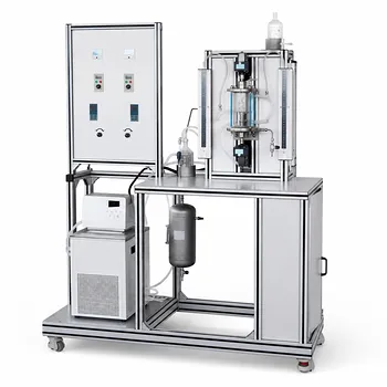
The most reliable method in a pilot plant context is the experimental determination under steady-state conditions, because it directly captures the real behavior of your specific heat exchanger geometry, fluid fouling state, and operating regime. However, this experimental value must be critically interpreted alongside theoretical calculations and empirical benchmarks to ensure measurement validity and to extract the underlying physical understanding. The three primary approaches—theoretical summation of resistances, controlled experimental measurement, and comparison with industrial empirical ranges—are complementary, and the strongest experimental program uses all three in concert.
For any given unit operations pilot plant, the highest-confidence overall heat transfer coefficient (K) comes from a careful steady-state experiment using the heat balance and log mean temperature difference (LMTD). But to trust that number, you must validate it against both the theoretical resistance network and published empirical envelopes, while accounting for how K can vary with temperature and flow regime.
The Three Foundational Ways to Determine K
Theoretical Calculation: Assembling the Resistance Network
Every overall heat transfer coefficient is the inverse of a total thermal resistance built from multiple components. This method forces the student or researcher to understand the physical layers that govern heat flow.
The total resistance is the sum of the hot-side convective film resistance, the fouling layer resistances on each side, the conductive resistance of the tube wall, and the cold-side convective film resistance.
In educational pilot plants, you can measure or calculate the individual film coefficients (hᵢ and hₒ) by varying flow velocities and observing the change in Reynolds number. The wall resistance (xₘ/kₘ) is known from tube dimensions and material. The fouling factors (hₒₐ and hᵢₐ) can be estimated from the service or tracked over time.
The theoretical route is powerful for teaching the fundamentals, but its absolute accuracy depends on high-fidelity input data—especially the film coefficients, which are sensitive to fluid properties and geometry.
Experimental Determination: The Definitive Value for Your Setup
Operating the pilot plant at steady state and measuring the four terminal temperatures and the mass flow rates of both fluids gives you the heat duty, Q. With the heat transfer area A known from the exchanger geometry, the famous rate equation Q = K · A · ΔTₗₘ yields the measured K directly.
This is the most reliable method for characterizing the performance of that specific unit under those exact conditions. The LMTD method properly accounts for the temperature profile shape in a counter‑ or co‑current flow.
The accuracy of this approach hinges on reaching true thermal steady state and on precise instrumentation. Small errors in temperature measurement near the exchanger inlets and outlets can propagate into large uncertainties in K.
Empirical Estimation: Industrial Ranges as a Sanity Check
Every heat transfer service has a well-documented range of typical K values. These are not design targets but rather “reality check” envelopes that can immediately highlight gross errors in experimental data.
For example, water-to-water systems in pilot-scale shell-and-tube exchangers typically fall in the range of 850–1700 W/(m²·°C). Water-to-steam condensation yields 1420–4250 W/(m²·°C), while air or flue gas coolers may be only 17–280 W/(m²·°C).
These empirical ranges are invaluable for student laboratories. If a student’s calculated K for a water‑water experiment is 6000 W/(m²·°C), it almost certainly indicates a measurement fault rather than a miraculous new heat transfer surface. Empirical baselines are a fast, low-cost filter for experimental plausibility.
When Simple Methods Are Not Enough: Coping with Variable Conditions
The Problem of Temperature‑Dependent K
The classic LMTD method assumes K is constant along the length of the exchanger. In real pilot plants handling fluids with strong viscosity or thermal conductivity changes, this assumption can break down.
When fluid properties shift significantly, K varies with local temperature. If the variation is linear, you can use a modified logarithmic expression that incorporates the K values at both ends of the exchanger (Kₒ₁ and Kₒ₂). For highly non‑linear variation, the reliable path is to divide the exchanger into small segments, assume a constant K within each segment, and integrate numerically. Pilot plants with many intermediate temperature taps make this segmentation method powerfully accurate.
Wilson Plot: The Gold Standard for Reactor Pilot Plants
In stirred reactor pilot plants, the overall coefficient K depends strongly on agitation. The Wilson plot method isolates the maximum heat transfer coefficient (Uₘₐₓ) elegantly.
By running cooling curves at multiple stirring speeds and plotting 1/K versus n^(−2/3) (where n is the stirrer speed), you obtain a straight line whose y‑intercept equals 1/Uₘₐₓ. This method is independent of the solvent used and is considered the most reliable way to characterize a reactor’s heat transfer capability in a teaching or research pilot facility. A quick single‑point approximation under maximum stirring speed with water gives a ballpark Uₘₐₓ for larger‑scale work.
Understanding the Trade‑Offs and Pitfalls
No method is flawless, and recognizing the limits builds true reliability.
The experimental K you painstakingly measure is strictly valid only for the exact geometry, fluid pairs, flow rates, and fouling state present during the test. Extrapolating it to a different scale or a slightly different fluid can lead to serious design errors. Similarly, empirical ranges are broad; choosing a low‑end value makes the pilot plant exchanger oversized, which may mask performance issues while increasing capital cost. Choosing a high‑end value risks an under‑sized unit that cannot meet thermal duty.
Fouling is a silent variable. Pilot plants often operate with clean fluids, producing a high K that will never be sustained in an industrial environment. To compensate, experienced practitioners deliberately include a fouling factor when using pilot‑plant data for scale‑up design.
Finally, relying on a single experimental run without cross‑checking against theoretical resistances or empirical baselines is a recipe for undetected systematic errors. Multiple runs, range‑finding experiments, and a convergence of all three methods provide the highest reliability.
Making the Right Choice for Your Pilot Plant Goal
Your selection of the most appropriate K‑determination method must align with the purpose of the experiment.
- If your primary focus is fundamental education: Begin with the theoretical resistance network to teach the physics, then conduct a steady‑state experiment and compare the measured K with the theoretical prediction. Use the empirical range as a quick sanity check.
- If your primary focus is scale‑up design from pilot data: Measure K experimentally under several representative operating conditions, then forcibly include conservative fouling factors and cross‑reference with industrial empirical ranges for the target service to ensure a safe design margin.
- If your primary focus is reactor heat transfer characterization: Use the Wilson plot method—it is the most reliable way to extract the vessel limit (Uₘₐₓ) independent of the test fluid, and the intercept eliminates the influence of internal film coefficients.
- If your primary focus is rapid data verification or troubleshooting: First compare the experimental K against the well‑known empirical envelopes for the fluids used. If the value falls within the expected band, your instrumentation and LMTD calculation are likely sound; if not, inspect the measurement chain immediately.
The reliable determination of the overall heat transfer coefficient is never a single‑number exercise. It is a convergence of experiment, theory, and empirical context—a process that turns a simple pilot‑plant measurement into a true lesson in engineering judgment.
Summary Table:
| Method | Core Principle | Best Use Case | Key Limitation |
|---|---|---|---|
| Theoretical Calculation | Sums convective & conductive resistances | Teaching fundamentals & initial designs | Sensitive to fluid property assumptions |
| Experimental (LMTD) | Uses steady-state heat balance ($Q = K A \Delta T_{lm}$) | Characterizing specific pilot units | Vulnerable to temperature sensor errors |
| Empirical Estimation | Benchmarks against industry ranges | Fast sanity checks & error filtering | Broad ranges, not for precise design |
| Wilson Plot | Plots $1/K$ vs. stirrer speed ($n^{-2/3}$) | Stirred reactor characterization | Requires multiple runs at variable speeds |
Optimize Your Heat Transfer Experiments with LABPARK
Are you looking to equip your lab with state-of-the-art training systems? LABPARK provides premium Educational and Vocational Unit Operations Pilot Plants in chemical engineering, bioprocess & biotech, and environmental & water treatment. Designed specifically for universities, research institutes, and enterprises, our pilot plants deliver precise, real-world data to help students and researchers master heat transfer coefficients and unit operations.
Contact LABPARK Today to discuss your laboratory requirements and get a customized solution!
Related Products
- Comprehensive Heat Transfer Coefficient Determination Educational Unit Operations Pilot Plant
- Solid Spherical Heat Transfer Coefficient Determination Educational Chemical Engineering Pilot Plant
- Shell and Tube Heat Exchanger Heat Transfer Coefficient Determination Educational Pilot Plant
- Circulating Wind Tunnel Drying and Convective Heat Transfer Coefficient Determination Educational Pilot Plant
- Comprehensive Multi-Modal Heat Transfer Unit Operations Pilot Plant for Engineering Training
People Also Ask
- Why is the study of thermal boundary layers and Prandtl numbers critical in heat transfer unit operations pilot plants?
- When is ε-NTU preferred over LMTD in pilot plants? Predict heat exchanger performance without iteration.
- Why is the prevention of scale formation on heat exchanger surfaces a critical learning objective? Key Lessons
- How do unit conversions affect pilot plant calibration? Avoid errors in heat transfer data analysis
- How is the effective thermal conductivity of a dilute particle suspension calculated? A Pilot Plant Guide