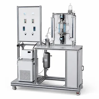
Sparged gas-liquid reactors—columns where gas is bubbled through liquid with no mechanical agitation—offer a unique mix of simplicity and complexity for pilot-plant experiments. Their operational advantages center on eliminating moving parts, which cuts maintenance and cost while providing robust solids handling and high heat transfer rates per unit volume. The key disadvantages are severe liquid‑phase backmixing, high pressure drops that become critical at low operating pressures, and loss of gas–liquid interfacial area through bubble coalescence, especially when the column height‑to‑diameter ratio exceeds 12. Understanding how these factors interact with your experimental goals is essential for designing a pilot‑plant study that yields meaningful, scalable data.
The core trade‑off: Sparged reactors remove mechanical seals and agitators, slashing downtime and capital expense, but they introduce unavoidable liquid backmixing and pressure drop. In a pilot plant, this means you trade mechanical simplicity for hydrodynamic complexity—your kinetic data will be colored by dispersion, and your column geometry will directly dictate mass‑transfer performance. Recognizing these limits lets you decide when a bubble column truly serves your experimental needs, and when a mechanically agitated system is worth the extra hardware.
The Operational Advantages That Make Sparged Reactors Attractive for Pilot Plants
Mechanical Simplicity Keeps Costs and Maintenance Low
With no moving parts—no impellers, shafts, or mechanical seals—a sparged reactor eliminates the most common failure points in chemical pilot plants.
This directly reduces routine maintenance, spare‑parts inventory, and the risk of unplanned shutdowns, which is especially valuable during long‑duration catalyst deactivation studies or when testing corrosive fluids.
The capital cost of a bubble column is often substantially lower than that of an equivalent stirred tank, because you avoid expensive agitator drives and high‑pressure mechanical seals.
For an academic lab or a pilot‑scale research unit with a limited budget, this simplicity can free up resources for better instrumentation or a wider matrix of experimental conditions.
Excellent Solids Handling and High Heat Transfer Rates
Because the gas sparging alone provides liquid circulation, bubble columns naturally keep solid particles in suspension as long as the superficial gas velocity remains above the minimum needed.
This makes them ideal for slurry‑phase catalytic reactions where you want to test a catalyst without worrying about a mechanical stirrer grinding or bypassing the particles.
Sparged reactors also deliver high heat transfer coefficients per unit reactor volume, even without mechanical agitation.
The rising gas bubbles generate a chaotic, well‑mixed liquid phase that promotes efficient heat removal through the wall or internal cooling coils.
For exothermic reactions, this means you can maintain precise temperature control using straightforward, validated semi‑empirical correlations that account for the gas–liquid dynamics at your pilot scale.
Ability to Handle Large Gas Throughputs and Gas Recycling
Industrial bubble columns routinely operate with high gas flow rates; pilot‑scale sparged systems let you replicate those conditions without the foaming or flooding problems that can plague agitated vessels at the same gas loads.
They also lend themselves to gas‑recycle configurations, because the column design naturally accommodates the pressure drop and flow uniformity needed for a recirculation loop.
The Operational Disadvantages That Complicate Pilot‑Plant Experiments
Liquid‑Phase Backmixing Masks True Kinetics
The most significant drawback of a sparged reactor is intense liquid backmixing, especially in the direction of flow.
Rather than behaving like a plug‑flow reactor, the liquid phase often resembles a continuously stirred tank, smearing the residence‑time distribution and making it difficult to extract intrinsic kinetic data from conversion measurements alone.
When your pilot‑plant goal is to determine rate constants or reaction orders, you must therefore account for this dispersion.
If the reaction is slow (Hatta number ( \sqrt{M} < 0.3 ), reaction occurs mainly in the bulk), backmixing directly dilutes the effective concentration driving force and can lead to an under‑prediction of the true rate if not corrected.
High Pressure Drop Can Skew Measurements and Impede Low‑Pressure Operation
Bubble columns impose a significant hydrostatic pressure drop, which is especially critical at the low operating pressures often used in lab‑scale pilot plants.
The pressure at the bottom of the column can be several hundred millibar above the headspace pressure, altering gas solubility and equilibrium composition—a fact that must be built into your thermodynamic models when studying reactions such as hydrogenation or oxidation.
At pilot scale, the effect is magnified if you use tall columns with high height‑to‑diameter ratios.
The resulting non‑uniform hydrostatic pressure profile makes it harder to interpret spatial concentration data and can complicate scale‑up, because the industrial unit will likely have a much lower L/dc and a different pressure‑gradient pattern.
Bubble Coalescence Cuts Interfacial Area—Especially in Tall Columns
As bubbles rise, they coalesce into larger, fewer bubbles, which dramatically reduces the gas–liquid interfacial area available for mass transfer.
The primary reference warns that when the column height‑to‑diameter ratio exceeds 12, this loss becomes severe; what starts as a fine dispersion at the sparger can turn into large slugs only a few diameters up the column.
For fast reactions (( \sqrt{M} > 3 )) where the reaction is mass‑transfer limited and occurs mostly in the liquid film, this drop in interfacial area becomes the process bottleneck.
A pilot plant using a tall sparged column for such a reaction will therefore give artificially low conversion, misleading you about the catalyst’s true potential or the reactor volume needed at full scale.
Limitations at Low Gas Flow Rates
When the superficial gas velocity falls below a critical threshold, the liquid circulation becomes too weak to keep solid catalyst particles suspended.
This is a particular concern in slurry bubble columns; you cannot simply “turn down” the gas flow to explore low‑throughput conditions without risking catalyst settling, which would create dead zones and invalidate the run.
For pilot‑plant studies that need to operate over a wide turndown range, this limitation often forces you to either add a mechanical agitator or to accept a smaller experimental window where gas‑induced mixing remains adequate.
Understanding the Trade‑offs in Practice
When the Reaction Regime Favors a Sparged Column
The Hatta number offers a clear decision rule.
Slow reactions (( \sqrt{M} < 0.3 )) need a large liquid holdup, so bubble columns—with their deep liquid pool and good bulk mixing—are an excellent choice.
Intermediate reactions (( \sqrt{M} \approx 1 )) also work well, provided you control column height to avoid the coalescence‑limited zone.
Fast reactions (( \sqrt{M} > 3 )), however, demand a high interfacial area and are poorly served by a tall bubble column.
In that regime, the pilot plant should instead be configured with a spray tower, a packed column, or a mechanically agitated vessel where bubble break‑up can be sustained.
Scale‑Up Pitfalls You Must Guard Against
Pilot‑scale sparged reactors typically have small diameters (70–150 mm) and high L/dc ratios (often 3:10), while industrial versions usually operate with lower L/dc (1:2) and lower superficial velocities.
This difference means that the backmixing patterns and pressure‑drop profiles you observe at pilot scale will not map linearly onto a larger reactor; scale‑up must be done with validated computational or residence‑time‑distribution models that account for the altered hydrodynamics.
Another trap is neglecting the hydrostatic head when translating data.
A 2‑m‑tall pilot column might have a bottom pressure 0.2 bar above the top; an industrial column 10 m tall would see a differential of 1 bar or more, profoundly affecting solubility and equilibrium.
Experiments must therefore be designed to measure, or at least model, that gradient.
Keeping Heat Transfer Reliable Without an Agitator
Although sparged reactors lack the fine‑tuning of a variable‑speed impeller, the natural turbulence induced by the gas is often sufficient for good heat transfer.
You can design the cooling coil or jacket based on well‑established semi‑empirical correlations that link the gas superficial velocity, the column diameter, and the physical properties of the liquid to the overall heat transfer coefficient.
The key operational decision is to ensure the gas flow never falls below the point where the heat transfer coefficient drops too far—just as you must avoid solids settling.
This interconnectivity of gas rate, suspension, and cooling is a central design constraint for any sparged pilot reactor.
Making the Right Choice for Your Pilot Plant Experiment
The choice between a sparged bubble column and a mechanically agitated system hinges squarely on your experimental priorities. Use the following guide to align the reactor type with your goals.
- If your primary focus is low‑maintenance, cost‑effective operation: Choose a sparged column. The absence of seals and agitators minimizes downtime, making it ideal for long‑term catalyst aging tests or corrosive environments where seal failure would be a constant headache.
- If your primary focus is extracting intrinsic kinetics from liquid‑phase reactions: Be cautious with a sparged reactor; backmixing will convolute the data. Either pair it with a detailed residence‑time‑distribution study, or switch to a mechanically agitated vessel that can approach plug‑flow behavior.
- If your primary focus is handling high gas throughputs and slurry solids: A bubble column is your best bet, provided you keep the gas velocity above the catalyst‑suspension threshold and control the L/dc ratio—stay below 12 to preserve interfacial area.
- If your primary focus is a fast, mass‑transfer‑limited reaction (Hatta >3): Avoid tall sparged columns. Opt instead for a spray tower, a packed column, or a stirred reactor with a secondary impeller near the gas‑liquid interface to maximize specific interfacial area.
- If your primary focus is precise temperature control during exothermic reactions: Sparged reactors can deliver high heat transfer rates, but you must implement validated semi‑empirical correlations for your specific coil‑ or wall‑cooled configuration and confirm that the gas rate never dips below the minimum needed for uniform cooling.
Understanding the interplay between mechanical simplicity, backmixing, pressure drop, and bubble dynamics transforms the sparged reactor from a simple glass column into a powerful tool for targeted, scalable chemical engineering experiments.
Summary Table:
| Aspect | Advantages | Disadvantages |
|---|---|---|
| Mechanics | No moving parts, low maintenance & CAPEX | Complex hydrodynamics, lacks agitation tuning |
| Mass Transfer | High gas throughput, solid suspension | Bubble coalescence reduces interfacial area |
| Kinetics & Flow | High heat transfer, suits slow reactions | Liquid backmixing masks true kinetic data |
| Pressure | Good for uniform temperature control | High hydrostatic pressure drop at low pressures |
Scale Up Your Chemical Engineering Experiments with LABPARK
Selecting the right reactor configuration is critical for generating reliable, scalable data. LABPARK offers high-quality Educational and Vocational Unit Operations Pilot Plants in chemical engineering, bioprocess & biotech, and environmental & water treatment. Designed specifically for universities, research institutes, and enterprises, our systems help you master complex gas-liquid hydrodynamics and optimize your research outcomes.
Need help configuring your pilot plant? Contact our technical experts today to find the perfect solution for your lab!
Related Products
- Dual-Drive Stirred Gas-Liquid Mass Transfer Coefficient Determination Pilot Plant
- Micro-Scale Gas-Solid Catalytic Reaction Educational Pilot Plant
- Fixed Bed Gas Solid Catalytic Reaction Educational Pilot Plant
- Fluidized Bed Gas Solid Catalytic Reaction Educational Pilot Plant
- Multi-Stage Stirred Tanks in Series Residence Time Distribution and Mixing Performance Determination Educational Pilot Plant
People Also Ask
- How does column packing affect absorption intensification, and how is it evaluated experimentally?
- Why Compare Membrane-Reservoir Models with Pilot Plant Data? Ensure Successful Process Scale-Up
- Why is pilot plant gas absorption lower than isothermal model predictions? Interfacial heating explained.
- Which interphase forces dominate gas dispersion in stirred reactors? Master Gas Holdup Models
- What key factors influence the rate of diffusion in liquids? Optimize Mass Transfer Pilot Plant Design