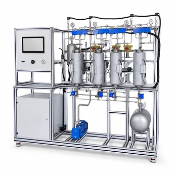
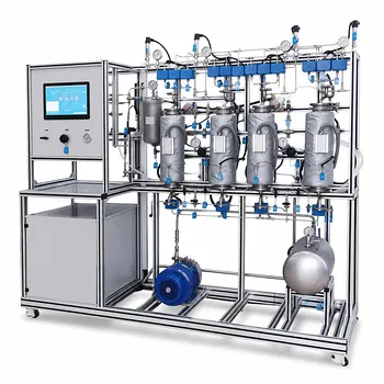
Your breakthrough study is the blueprint—it directly translates adsorbent performance from a flat disc into the surface area your pilot cartridges need. By pumping your process stream through a small, controlled lab-scale disk and monitoring when the impurity escapes, you determine the carbon life (volume treated per square foot), which then becomes the scaling factor for calculating the full cartridge area and minimum run time.
A carbon adsorption breakthrough study isn’t just a screening tool; it’s a predictive scaling instrument. It defines how much impurity a unit area of adsorbent can handle before failure, then uses that limit to size larger cartridge systems without trial-and-error guesswork.
What a Breakthrough Study Actually Reveals
The lab experiment does one critical thing: it pins a number to the carbon’s exhaustion point under your specific flow conditions. That number—expressed as volume per unit surface area (e.g., L/ft²)—becomes the pivot for all subsequent scale-up calculations. Without it, you’d be overlaying arbitrary safety factors and risking both underperformance and waste.
Setting Up the Lab-Scale Disc for Real-World Relevance
The study begins by selecting a small, representative disc of the chosen adsorbent, often cut from a sheet or packed into a filter housing of minimal diameter.
You pump your actual process fluid—not a clean surrogate—through the disc at a controlled flow rate. A downstream detector, typically UV‑Vis for color or an appropriate sensor for metals, continuously records impurity concentration.
Reading the Breakthrough Curve to Extract Carbon Life
The detector’s output draws a curve: initially flat near zero, then an upward slope as the impurity starts breaking through. The breakthrough point is where concentration exceeds an acceptable threshold (often 5–10% of the inlet value).
The total volume passed up to that moment, divided by the disc’s surface area, gives the carbon life (e.g., 200 L/ft²). This single metric encapsulates both the adsorbent’s capacity and the kinetic realities of your flow rate.
How That Lab Number Scales to Pilot Cartridges
Once you have a carbon life, the leap to pilot sizing becomes straightforward arithmetic—provided you respect the assumptions the disc experiment baked in. The key is to match the total batch volume you intend to treat with the surface area that can handle it.
The Surface Area Calculation: From Batch Volume to Cartridge Count
Divide the total pilot batch volume (in liters) by the carbon life (in L/ft²) to obtain the required total surface area of the cartridges. If multiple cartridges are used in parallel, their combined area must meet or exceed that number.
For example, a 1000 L batch with a carbon life of 200 L/ft² demands 5 ft² of working surface. You then select cartridges—say, 1.0 ft² each—and use five in parallel.
Locking In Minimum Run Time with Experimental Flux
The disc experiment also records the flux (flow rate per unit area, e.g., L/min·ft²). This flux determines how quickly the batch can be processed without exceeding the adsorption kinetics you tested.
Multiply the flux by the calculated cartridge area to get the maximum process flow rate. Divide the batch volume by that flow rate to obtain the minimum operation time required to fully utilize the carbon’s capacity. Running faster would shift the breakthrough curve, invalidating the life you measured.
Understanding the Scale-Up Trade-offs and Pitfalls
Scaling linear from a disc assumes that hydrodynamics, pressure drop, and contact time remain identical at the larger scale. In reality, cartridge geometry, bed depth, and fluid distribution rarely match a flat disc perfectly, introducing risks.
When Linear Scaling Begins to Fail
Channeling and uneven flow distribution can appear in full-sized cartridge housings but are absent in a tiny disc holder. Even minor bypassing reduces effective contact, making the actual carbon life shorter than predicted.
Pressure drop constraints may force you to operate at a lower flux than the lab test, altering the kinetic regime. If the lab disc ignored back-pressure effects, the pilot may need correction factors derived from supplementary pressure drop experiments.
Designing Out Scale Sensitivity with First-Principles Checks
The supplementary workflow of a pilot plant—defining the Design Space—directly addresses this. Parameters like linear velocity and bed residence time become scale-sensitive. By ensuring your cartridge selection maintains the same linear velocity as the disc, you minimize the deviation.
Additionally, Design of Experiments (DOE) on the disc test can map how flux and impurity concentration interact to shift breakthrough. That map helps you anticipate non-linear scaling and set safe operating ranges for the pilot.
Making the Right Choice for Your Pilot Goal
Your final cartridge sizing should reflect your primary objective—whether it’s minimizing carbon cost, ensuring absolute impurity clearance, or maximizing throughput within a shift.
- If your primary focus is cost efficiency: Choose a conservative carbon life (e.g., stop at 5% breakthrough) and validate with a small-scale pilot run before buying all the cartridges. This prevents disc-estimate optimism from triggering an early media replacement.
- If your primary focus is process speed: Run the disc at the highest flux you can physically achieve on the pilot skid, then size cartridges strictly from that flux. Accept that the carbon life may drop, but you’ll meet production schedules.
- If your primary focus is robustness for metal removal: Use a safety factor of 1.2–1.5 on surface area and consider serial or lead-lag cartridge arrangements. Metal leakage can happen abruptly, so conservative sizing prevents batch failures during concentration spikes.
- If your primary focus is regulatory or validation readiness: Document the disc test as part of your Design Space, linking flux, carbon life, and impurity loading with a DOE. Then confirm at pilot scale using multivariate statistical process control (MSPC) to prove the relationship holds under normal variability.
A well-executed breakthrough study turns adsorption cartridges from a guess into an engineered step—giving you the confidence that your pilot will perform exactly as the lab predicted, and no more.
Summary Table:
| Parameter | How to Measure (Lab Scale) | Scale-Up Application |
|---|---|---|
| Carbon Life | Volume treated per unit area (L/ft²) before breakthrough | Determines required total cartridge surface area (Batch Volume ÷ Carbon Life) |
| Flux | Flow rate per unit area (L/min·ft²) | Determines maximum process flow rate and minimum run time |
| Breakthrough Point | Volume where impurity concentration exceeds 5–10% | Defines the limit of carbon capacity and run-time calculations |
| Safety Factor | 1.2–1.5 multiplier (especially for metal removal) | Compensates for channeling, pressure drops, and bypassing in full-scale housings |
Scale Up Your Processes with LABPARK Pilot Plants
Transitioning from lab-scale breakthrough studies to pilot-scale filtration requires reliable, industry-grade equipment. LABPARK provides premium Educational and Vocational Unit Operations Pilot Plants in chemical engineering, bioprocess & biotech, and environmental & water treatment, tailored specifically for universities, research institutes, and enterprises.
Whether you are training the next generation of engineers or scaling up industrial water treatment processes, our pilot plants deliver the accuracy, reliability, and scaling performance you need.
Contact our experts today to discuss your process scale-up needs!
Related Products
- Low Concentration Carbon Dioxide Capture Pressure Swing Adsorption Educational Pilot Plant
- Carbon Dioxide Adsorption and Capture Educational Unit Operations Pilot Plant
- Carbon Dioxide Absorption and Desorption Educational Pilot Plant for Carbon Capture Studies
- Multi-Component Gas Pressure Swing Adsorption Pilot Plant for Unit Operations Education
- Bench Scale Carbon Dioxide Capture Educational Unit Operations Pilot Plant
People Also Ask
- How does operating pressure influence the transition between absorption and desorption in a CO2 pilot plant?
- What unit operations are critical for CCUS training pilot plants? Build hands-on engineering expertise.
- How can pilot plants show tail gas vs flue gas CO2 capture differences? Key educational insights.
- What are the differences between post- and pre-combustion carbon capture training pilot plants?
- How do temperature variations affect CO2 transport models in pilot plants? Model vs Reality