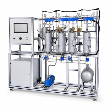
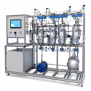
The pilot plant is a miniature chemical plant, not just a piece of lab equipment. It demonstrates industrial gas scrubbing by forcing a polluted gas stream upward through a column while a liquid solvent (like a dilute sodium hydroxide solution) cascades downward over a bed of structured packing. This countercurrent contact maximizes the surface area for the chemical reaction that neutralizes the pollutant. To prevent the catastrophic failure known as column flooding—where liquid is physically blocked from descending—the single most critical practice is to balance the gas and liquid flow rates and continuously monitor the pressure drop across the packed bed to keep it within a safe, stable window.
While the pilot plant simply shows how gas gets scrubbed, its greatest experimental value is in teaching you how to prevent its own destruction. You’re not just running a reaction; you’re navigating the hydraulic limits of the column, where the sweet spot for safe, efficient operation is defined entirely by a narrow range of pressure drop readings.
From Classroom Theory to Pilot Plant Reality
The Core Demonstration of Mass Transfer
The pilot plant takes the abstract theory of absorption and makes it tangible. The packing material—often Raschig or Pall rings—exists solely to create a massive wetted surface area where the gas and liquid phases can meet.
Without this packing, the gas would bubble uselessly through the liquid. With the packing, the liquid spreads into a thin film, and the target pollutant gas molecule must diffuse into that film to react. This demonstration allows you to calculate the Height of a Transfer Unit (HTU) and the Number of Transfer Units (NTU) , the foundational metrics for scaling up to an industrial-sized scrubber.
Visualizing Chemical vs. Physical Absorption
The pilot plant clearly distinguishes between a slow physical process and a fast chemical one. When scrubbing carbon dioxide with plain water, the driving force is limited by solubility, requiring a taller column.
Introduce a reactive solvent like an amine or sodium hydroxide, however, and the mechanism changes. The solute reacts instantly upon contact, effectively destroying it and maintaining a near-zero concentration at the interface. This showcases the power of chemical absorption to dramatically reduce equipment size and enhance removal efficiency.
The Hydraulic Battle: Understanding Column Flooding
The Physics of a Drowning Column
Flooding is a purely hydraulic failure. In a stable column, gravity pulls the liquid down while the gas’s upward drag force is manageable. But as you increase the gas velocity, the frictional force on the liquid film becomes too great.
The liquid begins to accumulate, or “load,” in the void spaces of the packing. The point at which the upward gas force equals the gravitational force on the liquid is the flood point—liquid can no longer descend and is instead blown out the top of the column. This leads to a complete breakdown in separation efficiency.
The Critical Parameter: Decoding the Pressure Drop
Column flooding cannot be precisely predicted by flow rates alone; it must be tracked by its primary symptom: an exponential increase in pressure drop (DP) . The gas has to push harder to get past the accumulating liquid. For a typical random-packed column, the numbers are clear:
- The Safe Operating Zone: The pressure drop should remain at or below 1.5 inches of water per foot of packing (in/ft) . This represents roughly 95% of the flood point and ensures stable performance.
- The Flood Point: At a pressure drop of 2.0 in/ft , most randomly packed columns reach their absolute hydraulic limit and flood.
- The Low-Load Danger Zone: If the pressure drop falls too low, typically below 0.05 in/ft , you have the opposite problem. The liquid rate is insufficient to wet the packing, causing it to channel down the walls and bypass the gas entirely.
Navigating the Operational Window and Its Trade-offs
Why a High Liquid Ratio Isn’t Always Better
Intuitively, you might think more solvent means better scrubbing, but this ignores column hydraulics. The liquid-to-gas ratio (L/G) has a direct and punishing trade-off.
A higher L/G ratio increases liquid holdup—the volume of liquid clinging to the packing at any moment. This liquid consumes the free space meant for the gas to flow. By constricting the gas’s pathway, you actually lower the velocity at which flooding occurs. This means an overly aggressive liquid flow rate can cap your gas throughput and force the column into a premature flood, a critical lesson the pilot plant illustrates perfectly.
The Unique Value of Inducing Controlled Failure
Industrial operators rigidly design systems to run at 80% of the flooding velocity to guarantee safety. Educational pilot plants, however, are built differently. Their real purpose is to let you safely break the process.
By deliberately pushing the column from a stable region into the loading zone and finally to the flood point, you see theory become hardware. You can watch the differential pressure spike on the sensors, observe liquid backing up, and directly link this physical chaos to the abstract pressure drop correlation charts in a textbook. This destructive testing forges a visceral understanding that safe, stable data can never provide.
The Role of Packing Geometry and Fluid Properties
The flood point isn’t a fixed number for all systems; it’s a function of the physical components. The pilot plant allows you to test these variables:
- Packing Factor ($\phi$): Packing with a lower factor, which typically has more open space, offers less frictional resistance and yields a higher flooding velocity.
- Fluid Properties: A denser liquid ($\rho_L$) is pulled down by gravity more forcefully and resists flooding. Conversely, a dense gas ($\rho_V$) or a viscous liquid ($\mu_L$) increases drag and makes the column far more susceptible to flooding at a lower gas velocity.
Making the Right Choice for Your Experimental Goal
Your operational strategy must align with what you are trying to learn. The beauty of the pilot plant is you can target a specific lesson by simply altering your flow rates.
- If your primary focus is to safely demonstrate steady-state absorption and calculate mass transfer efficiency: Maintain the pressure drop firmly in the middle of the safe zone, between 0.1 and 1.0 in/ft, with a conservative liquid-to-gas ratio to ensure consistent wetting without the risk of loading.
- If your primary focus is to experimentally map the loading point and identify the column’s hydraulic limit: Slowly and methodically increase the gas velocity while holding the liquid rate constant, watching for the pressure drop curve to inflect sharply. The goal here is to approach the 1.5-2.0 in/ft range to capture the flood data point.
- If your primary focus is understanding the lower limits of operation and the problem of channeling: Reduce the liquid flow until the pressure drop crashes below 0.05 in/ft. Pair this with a visual inspection if possible, or compare the resulting poor absorption performance against a well-wetted run to quantify the efficiency loss.
The packed absorption column pilot plant ultimately teaches you that a successful chemical process is first a successful hydraulic process. Master the pressure drop, and you master the entire operation.
Summary Table:
| Operating Zone | Pressure Drop (DP) Range | Hydraulic Status & Impact |
|---|---|---|
| Safe Zone | ≤ 1.5 in/ft | Stable performance, optimal mass transfer |
| Flood Point | ≥ 2.0 in/ft | Liquid accumulation, complete loss of efficiency |
| Low-Load Zone | < 0.05 in/ft | Liquid channeling, poor wetting of packing |
Bring Industrial Reality to Your Lab with LABPARK
Are you looking to bridge the gap between classroom theory and industrial practice? LABPARK provides state-of-the-art Educational and Vocational Unit Operations Pilot Plants in chemical engineering, bioprocess & biotech, and environmental & water treatment.
Designed specifically for universities, research institutes, and enterprises, our pilot plants allow students and researchers to safely master critical processes like gas scrubbing and column hydraulics.
Ready to upgrade your laboratory capabilities? Contact LABPARK today to discuss your custom pilot plant requirements!
Related Products
- Packed Bed Absorption Educational Unit Operations Pilot Plant
- Absorption and Desorption Educational Unit Operations Pilot Plant
- Multimodal Absorption and Desorption Pilot Plant for Unit Operations Training
- Pressure Swing Adsorption Educational Unit Operations Pilot Plant
- Bench Scale Dual Column Gas Separation and Capture Educational Pilot Plant
People Also Ask
- How Do Flow Regimes Transition in Packed Bed Pilot Plants? Key Scale-up Insights
- How does reactant concentration determine absorption column control? Gas-film vs. dual-film.
- How is the packing height of an absorption column calculated? Master HTU & NTU Concepts
- How does the wall effect impact packed-bed conversion? Essential pilot plant scale-up tips.
- How does static vs. operating holdup affect pilot plant calibration? Avoid Critical Scale-Up Errors