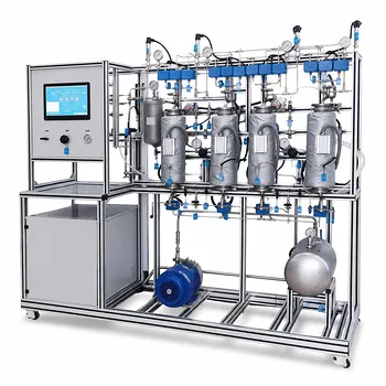
Stable atomization in a spray coating pilot system hinges on one truth: the fluid’s viscosity at the nozzle’s high shear rates and its sensitivity to solids content dictate everything. In the intense shear field inside a spray nozzle (typically well above 200 s⁻¹), complex non-Newtonian, shear-thinning behavior collapses to a practically constant viscosity. However, that constant viscosity grows exponentially as the solids concentration increases. This forces the operator to re-engineer the feed pump pressure and the atomizing gas flow to maintain the desired droplet size and spray stability.
The critical takeaway: Complex shear-thinning rheology simplifies to a steady high‑shear viscosity during nozzle atomization, but that viscosity is exponentially amplified by solids content. Controlling the resulting droplet size requires proactive, physics‑driven adjustments to pump discharge pressure and atomizing gas flow—not just a simple valve tweak.
The Rheology of Spray Coating Fluids
Non-Newtonian Behavior Yields to High‑Shear Simplicity
Coating formulations like HPMC or PVA solutions are classic shear‑thinning fluids. At rest or low flow, entangled polymer chains create high resistance.
But inside a spray nozzle, shear rates quickly soar past 200 s⁻¹. Under this violent deformation, the polymer chains align, and the viscosity stabilizes to a constant, nearly Newtonian value.
This is a powerful simplification for pilot‑plant operation: you can treat the atomization viscosity as a single, steady number for a given formulation.
Solids Content Drives an Exponential Viscosity Surge
As you increase the percentage of dissolved or suspended solids, the viscosity does not rise in a straight line. It climbs exponentially.
A seemingly small formulation change—jumping from 10 % to 15 % solids—can multiply the high‑shear viscosity several times over. This viscosity surge is the dominant rheological shock your system must absorb.
Understanding this exponential relationship is what allows a student or researcher to predict when a coating recipe will force a complete reconfiguration of the atomization setup.
From Viscosity to Droplet Size: The Atomization Mechanism
How Viscosity Resists Droplet Breakup
Atomization is a tug‑of‑war. Disruptive aerodynamic forces from the gas stream try to tear the liquid apart, while cohesive forces—primarily viscosity—resist breakup.
Higher viscosity means the liquid filament stretches further before snapping into droplets. The direct result is a much larger Sauter Mean Diameter (SMD).
Under constant atomization gas flow, a formulation change that increases solids from 10 % to 15 % can cause the SMD to explode from 52.4 µm to 116.8 µm. Coating uniformity collapses when droplets can no longer spread and level properly.
The Pilot System’s Clinical Symptoms
In the pilot plant, this rheological shift shows up immediately. A high‑viscosity feed increases the back‑pressure on the feed pump.
If the pump setting remains unchanged, the nozzle’s liquid orifice may not develop the pressure drop needed to form a stable jet. The spray pattern begins to sputter, droplet distribution coarsens, and the target film quality vanishes.
These symptoms are not equipment failures; they are direct physical feedback from the fluid properties. Reading them correctly is the core skill a pilot‑plant operator learns.
Engineering the Solution: Adapting Pilot System Parameters
Feed Pump Configuration and Nozzle Pressure
To restore stable atomization with a higher viscosity, you must adjust the fluid delivery side. A positive‑displacement pump must deliver a higher discharge pressure, or a larger liquid orifice must be selected to avoid cavitation.
The nozzle’s liquid passage requires sufficient pressure drop to accelerate the fluid to the velocity at which the gas stream can break it. Using the stabilized high‑shear viscosity, you can calculate the needed pump pressure with simple fluid dynamics.
This is why the primary reference emphasizes that understanding rheology allows students to correctly configure feed pumps—not guess.
Adjusting Atomization Gas Flow Rates
The atomizing gas flow is your main lever to physically overcome viscosity. A more viscous liquid demands more kinetic energy to rip its sheet into fine droplets.
You can deliver this energy by increasing the atomization air pressure, which raises the gas‑to‑liquid mass ratio (ALR). Pilot experiments repeatedly show that boosting the gas flow brings the SMD back toward the target range when solids content rises.
The operator’s task becomes an iterative loop: measure the resulting droplet size, adjust the gas pressure, and re‑characterize the spray until the required quality is restored.
Understanding the Trade‑offs
Over‑Atomization and Orifice Erosion
Turning up the gas flow is not a cost‑free solution. Excessive atomization air velocity can cause droplet bounce‑back, overspray, and rapid erosion of the nozzle orifice.
In a pilot plant, these translate into higher maintenance intervals and material waste that may silently erode the process economics. The line between “adequate atomization” and “abrasive destruction” is sometimes thin.
The Limits of Rheological Compensation
Every system has an operational envelope baked into its fluid properties. If the viscosity becomes extreme due to very high solids loading, even maximum gas flow fails to produce fine droplets.
The liquid may exit as a pulsating jet, refusing to break up. At this point, no hardware adjustment will help—reformulation of the coating solution is the only path forward.
Recognizing this ceiling is just as important as learning to make adjustments. It teaches that pilot plants are diagnostic tools, not just production machines.
Making the Right Choice for Your Pilot Operation
Your fluid is the control variable. Match your operational response to the specific goal at hand:
- If your primary focus is maintaining a consistent droplet size (SMD) when scaling a coating formulation: Measure the high‑shear viscosity of your solution first. Then lock in a constant gas‑to‑liquid mass ratio and adjust pump pressure accordingly. This keeps the SMD on target even as solids content varies in small increments.
- If your primary focus is commissioning a new pilot spray system with unknown feed rheology: Map the viscosity‑versus‑solids curve at the expected high shear rates (above 200 s⁻¹). Then select a pump and nozzle combination capable of delivering the required pressure at the highest expected viscosity without entering the erosion‑prone gas‑flow range.
- If your primary focus is troubleshooting a spray that suddenly coarsens: Check for an unintended jump in solids content—evaporation, settling, or a formulation mistake. An exponential viscosity rise is the likely cause. Compensate with a modest gas‑flow increase, but first verify the pump isn’t already over‑pressured and the nozzle orifice isn’t showing signs of erosion.
Mastering the link between fluid viscosity and atomization turns your pilot plant from a mysterious black box into a predictable, controllable process.
Summary Table:
| Parameter / Property | Impact on Atomization | Recommended Adjustment |
|---|---|---|
| High Viscosity | Larger droplet size (SMD); increased pump back-pressure. | Increase pump discharge pressure or select a larger liquid orifice. |
| Elevated Solids Content | Exponential viscosity rise; sputtering and coarser spray. | Boost atomization gas flow rate to increase aerodynamic energy. |
| Excessive Gas Flow | Droplet bounce-back, overspray, and nozzle erosion. | Balance the gas-to-liquid mass ratio (ALR) within operational limits. |
Bring Precision to Your Process Engineering Education & Research
Optimizing fluid dynamics and atomization requires the right pilot setup. LABPARK provides advanced Educational and Vocational Unit Operations Pilot Plants in chemical engineering, bioprocess & biotech, and environmental & water treatment. Designed specifically for universities, research institutes, and enterprises, our systems empower students and researchers to master hands-on process control and scale-up challenges.
Ready to elevate your laboratory capabilities? Contact us today to discuss your custom pilot plant requirements!
Related Products
- Multi Functional Membrane Crystallization Educational Unit Operations Pilot Plant
- Carbon Material Thermal Pretreatment Multiphase Separation Educational Pilot Plant
- Multifunctional Membrane Separation Educational Pilot Plant with Ultrafiltration, Nanofiltration, Reverse Osmosis
- Educational Pressure Swing Adsorption Ethylene Capture Unit Operations Pilot Plant
- Carbon Dioxide Capture and Utilization Educational Pilot Plant for Unit Operations
People Also Ask
- Why is precise temperature control critical in crystallization pilot plants? Key to Scale-Up Success
- Control Crystallization Pilot Plant Secondary Nucleation: 4 Key Adjustments
- What key factors should be considered when configuring a crystallization unit operations pilot plant?
- How Crystal vs Amorphous Solids Guide Crystallization Pilot Plant Objectives
- What are the benefits of integrating online PAT tools like ATR-FTIR into crystallization unit operations pilot plants?