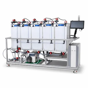
The blueprint for a pilot plant that turns toxic hexavalent chromium into a manageable solid starts with two tightly coupled stages. To demonstrate chemical reduction and precipitation of Cr⁶⁺ from industrial wastewater, a pilot system must integrate a reduction reactor — where acidic conditions and a dosing pump feed a reducing agent like ferrous sulfate — followed by a precipitation unit that raises pH to form insoluble chromium hydroxide, and finally a settler for sludge separation. Accurate dosing, real‑time ORP and pH monitoring, and a viewable flow path turn theoretical stoichiometry into an observable, hands‑on educational tool.
The real challenge isn’t just getting the chemistry right; it’s building a transparent, controllable system that lets students and researchers trace exactly how the toxic, dissolved Cr(VI) ion transforms into a particulate Cr(OH)₃ sludge they can measure, dewater, and account for in a mass balance.
The Core Chemistry: From Toxic Ions to Removable Solids
Why Oxidation State Matters
Hexavalent chromium (Cr⁶⁺) is a mobile, highly toxic anion, while trivalent chromium (Cr³⁺) is far less harmful and readily forms insoluble solids. Simply raising pH on Cr(VI)-laden wastewater does not remove it efficiently — you must first chemically reduce it to Cr(III). The biological and regulatory consequences of the oxidation state make this two‑step conversion non‑negotiable.
The Reduction Step
In the reduction reactor, the wastewater is acidified (typically below pH 3) and a reducing agent — commonly ferrous sulfate (Fe²⁺) or sodium bisulfite — is added under vigorous mixing. The Fe²⁺ ion donates an electron, transforming Cr(VI) into Cr(III) and forming Fe³⁺ as a co‑product. The oxidation‑reduction potential (ORP) gives an instantaneous electrochemical window into whether enough electrons have been delivered to drive the reaction to completion.
Precipitation by Solubility Control
Once all chromium is in the Cr(III) state, the pH is raised using an alkaline reagent like sodium hydroxide or lime. Because Ksp of chromium hydroxide (Cr(OH)₃) is exceedingly low, even modest hydroxide concentrations push the equilibrium toward solid formation. This is where abstract concepts like solubility product constants become tangible — students observe the turbidity point where precipitation begins and can relate it directly to the ion product exceeding Ksp.
Mapping the Chemistry onto Pilot Plant Design
Reactor Configuration and Staging
A two‑stage, continuous stirred‑tank reactor (CSTR) layout provides the clearest demonstration. The first CSTR hosts the acidic reduction; a second, slightly larger tank serves as the precipitation chamber. Clear, transparent vessels (glass or acrylic) allow direct visual tracking of the color change — the orange hue of Cr(VI) disappearing as the green‑blue tint of Cr(III) appears.
Dosing Systems and Chemical Feed
Precision is everything. The pilot plant needs dedicated peristaltic or diaphragm dosing pumps for acid, reducing agent, and base. Flow rates must be adjustable to simulate real‑world fluctuations in contaminant load. By requiring the operator to calculate the theoretical dosage based on influent Cr(VI) concentration (using Fe²⁺ stoichiometry), the system reinforces fundamental mass‑balance and chemical‑handling skills.
Monitoring and Control: pH and ORP
Real‑time sensors are the senses of the plant. An ORP probe in the reduction tank tells you the instant the electron‑exchange reaction has reached its endpoint, avoiding both under‑dosing (leaving toxic Cr(VI) in solution) and over‑dosing (wasting chemicals). Downstream, a pH probe in the precipitation tank confirms sufficient alkalinity to achieve the target hydroxide precipitation window (typically pH 8‑9 for Cr(III)). Connecting these sensors to a simple control loop or data‑logging system turns the pilot plant into a responsive, investigative platform.
Solid‑Liquid Separation Units
After precipitation, a settling column or lamella clarifier captures the chromium hydroxide floc. A conical bottom design lets the sludge compact and be withdrawn for mass‑balance analysis. For a complete educational experience, a small vacuum filtration or centrifuge stage can demonstrate sludge dewatering and help quantify the waste volume — linking operations directly to E‑factor calculations that compare waste generation across different treatment pathways.
Understanding the Trade‑offs in an Educational Pilot
No pilot design is perfectly universal; you must balance process fidelity against instructional clarity.
Transparency versus Industrial Realism
A fully automated, stainless‑steel system closely mirrors a real plant but hides the inner workings. For demonstration and experimentation, transparent glass reactors and exposed metering pumps typically deliver far more learning value, even if they sacrifice some pressure tolerances and long‑term wear resistance.
Batch vs. Continuous Operation
Batch operation simplifies sampling and stoichiometry verification — you can stop the process at each stage and quantify conversion directly. Continuous flow, however, teaches the challenges of residence‑time distribution, steady‑state control, and surge handling. A modular pilot that can switch between modes offers the best of both, but increases complexity and cost.
Sludge Handling and Interpretation
The sludge generated is often a mixture of chromium hydroxide and co‑precipitated iron hydroxides. If your learning objective focuses on pure metal recovery, you must design additional separation steps. If the goal is regulatory compliance, demonstrating that the final effluent Cr(VI) falls below 0.1 mg/L is the key endpoint, and the mixed sludge is a realistic by‑product.
How to Match the Pilot Design to Your Learning Goals
After defining your primary educational or research objective, tailor the unit operations accordingly.
- If your primary focus is teaching stoichiometry and mass balance: Build a transparent batch reduction tank with oversized chemical‑dosing controls and require operators to pre‑calculate the required ferrous sulfate mass based on known influent Cr(VI) concentration, then verify conversion with wet chemistry.
- If your primary focus is mastering process control and automation: Integrate ORP‑ and pH‑activated dosing pumps into a continuous‑flow system, challenging users to tune PID parameters and avoid controller‑induced oscillations that can release under‑treated effluent.
- If your primary focus is exploring precipitation chemistry and solubility equilibria: Add variable‑rate mixing, temperature control, and multiple sampling ports along the settling column to correlate residence time with particle size distribution and residual dissolved Cr(III) concentration, directly validating Ksp predictions.
- If your primary focus is holistic waste minimization and green chemistry: Include a dewatering stage and require a full waste‑product E‑factor calculation, then compare the chromium reduction‑precipitation route with an alternative (such as ion exchange) run on the same platform.
With each decision, you’re not just building a demonstration unit — you’re crafting a physical‑world hypothesis that lets every user measure, feel, and optimize the journey from toxic ion to harmless solid.
Summary Table:
| Stage | Process Objective | Key Equipment & Sensors | Visual Indicator |
|---|---|---|---|
| 1. Reduction | Reduce toxic Cr(VI) to Cr(III) under acidic conditions | Dosing pumps, ORP sensor, CSTR | Color shift from orange to green-blue |
| 2. Precipitation | Raise pH to form insoluble Cr(OH)3 solids | Alkaline pump, pH sensor, CSTR | Solution turns turbid with floc |
| 3. Separation | Separate sludge to clarify effluent | Settling column, clarifier | Sludge compaction & clear water |
Elevate Your Practical Engineering Education with LABPARK
Are you looking to bridge the gap between textbook theory and real-world industrial wastewater treatment?
LABPARK provides state-of-the-art Educational and Vocational Unit Operations Pilot Plants across chemical engineering, bioprocess & biotech, and environmental & water treatment. Engineered specifically for universities, research institutes, and enterprises, our systems offer:
- High Transparency: Glass and acrylic reactors for clear, step-by-step visual tracking of chemical reactions.
- Advanced Control & Monitoring: Integrated pH, ORP, and flow sensors for hands-on process automation experience.
- Flexible Configurations: Modular setups suitable for both continuous flow and batch operation research.
Empower your students and researchers to master heavy metal removal, mass balance calculations, and pilot-scale process control. Contact us today to request a quote or customize your pilot plant setup!
Related Products
- Methane Cracking Educational Unit Operations Pilot Plant
- Natural Product Extraction Unit Operations Training Pilot Plant
- Multi-Functional Special Distillation Educational Pilot Plant
- Solid Waste Pyrolysis and Refining Educational Pilot Plant for Unit Operations
- Dual-Mode Rectification Pilot Plant for Practical Training Unit Operations
People Also Ask
- How do ethane vs naphtha cracking influence teaching pilot plant analytical configurations? Key Design Guide
- How can flow-NMR be integrated with pilot plant reactors to monitor kinetics? A Complete Guide
- How do cracking temperature and residence time affect olefin yield? Pilot Plant Guide
- How do reactor pilot plants define QbD design space? Master chemical process scale-up.
- How are utility consumption rates integrated into chemical pilot plant economic evaluations?