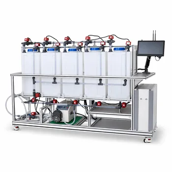
Prevent plugging by separating moisture-reactive vapors from the wet scrubber. When a gas stream contains chlorosilanes or similar moisture-reactive contaminants, it should first pass through an upstream condenser that cools and removes the reactive vapors before they contact water. The condensed material can then be collected for recycle, while the remaining gas enters the wet scrubber for final absorption without generating fouling liquids or precipitates inside the piping, packing, or column.
The central design principle is to prevent direct contact between moisture-reactive vapors and the scrubber liquid. Condensation and collection upstream of the wet scrubber convert the most problematic contaminants into a recoverable liquid and protect downstream equipment from hydrolysis-related blockage.
Why Direct Wet Scrubbing Causes Plugging
Moisture triggers hydrolysis
Compounds such as chlorosilanes react rapidly when introduced directly into a water-based scrubber. The reaction can generate hydrolysis products that are highly viscous, partially solid, or capable of forming precipitates.
This is not simply an absorption problem. The contaminant changes phase and chemistry inside the scrubber environment, where water, packing surfaces, piping, and spray nozzles provide many opportunities for deposits to form.
Deposits restrict flow paths
Viscous reaction products can accumulate in narrow piping, liquid distributors, demisters, nozzles, and column packing. Precipitates can also bridge across flow passages and progressively reduce gas or liquid throughput.
The result is rising pressure drop, declining mass-transfer performance, difficult cleaning, and unplanned downtime.
A wet scrubber cannot compensate for incompatible chemistry
Increasing water circulation or changing scrubber operating conditions does not eliminate the fundamental issue if the reactive vapor is allowed to contact water before it is removed. The unit operation must be arranged so that the incompatible reaction is prevented or moved to a controlled location.
How an Upstream Condenser Protects the Scrubber
Cool the gas before water contact
The incoming gas stream should pass through a condenser upstream of the wet scrubber. Cooling reduces the vapor pressure of the reactive contaminants and causes them to condense before they reach the water-based absorption stage.
The condenser therefore acts as a chemical compatibility barrier between the reactive vapor and the wet scrubber.
Collect the condensed liquid deliberately
Condensed chlorosilanes and related liquids must be directed to a collection system rather than allowed to drain into the scrubber or accumulate inside the condenser. The collection arrangement should provide a defined liquid outlet, appropriate containment, and a controlled route for recycle or disposal.
Recovered liquid can be recycled back into the process when its composition and operating objectives allow.
Send only the residual gas to the scrubber
After condensation and liquid removal, the remaining gas stream can enter the wet scrubber for final absorption. The scrubber then performs its intended function on the residual contaminants without being exposed to the bulk of the moisture-reactive vapor load.
This arrangement reduces the likelihood of viscous fouling and precipitate formation in the column and downstream piping.
Design Features That Support Reliable Operation
Provide sufficient condensation duty
The condenser must be capable of cooling the incoming gas enough to remove the reactive vapor fraction expected under the operating conditions. Its performance should be evaluated against gas flow, contaminant loading, inlet temperature, and the required degree of vapor removal.
An undersized or poorly controlled condenser can allow excessive contaminant carryover into the wet scrubber, recreating the original plugging mechanism.
Include effective liquid separation
Condensing the reactive material is only useful if the liquid is removed from the gas path. The design should therefore include a low-point collection arrangement and, where needed, gas-liquid separation features that limit entrainment into the scrubber inlet.
Liquid carryover can expose downstream equipment to the same hydrolysis risk that the condenser was intended to prevent.
Control where moisture is introduced
The condenser and its collection system should be arranged so that condensed reactive liquid does not unintentionally contact water or humidified surfaces. Any water wash, wet drain, or aqueous seal located upstream of the scrubber can become an uncontrolled reaction point.
The preferred sequence is cooling, condensation, liquid collection, and only then water scrubbing.
Monitor indicators of carryover and fouling
Operational monitoring should focus on evidence that reactive vapor is bypassing the condenser or that deposits are beginning to form. Useful indicators include condenser outlet temperature, scrubber inlet conditions, pressure drop across the scrubber, and changes in liquid collection rate.
A rising scrubber pressure drop or declining gas-flow capacity should be treated as a possible fouling signal rather than only as a routine hydraulic variation.
Understanding the Trade-offs
Condensation adds equipment and control requirements
An upstream condenser requires additional capital, utilities, instrumentation, space, and maintenance. It also introduces another unit operation that must remain available for the environmental treatment system to operate reliably.
Those costs are weighed against the operational consequences of repeated plugging, including cleaning, lost pilot-plant availability, damaged packing, and uncertain scrubber performance.
The condenser relocates the handling challenge
The reactive compounds do not disappear; they are transferred from the gas phase into a collected liquid. That liquid may still require compatible materials, closed handling, controlled drainage, recycling, or disposal.
The collection system must therefore be designed as part of the plugging-prevention strategy, not treated as an afterthought.
Incomplete removal can still create fouling
A condenser that removes only part of the reactive contaminant load may reduce, but not eliminate, the risk. The residual vapor can still hydrolyze after entering the wet scrubber, particularly if the remaining concentration is high or the condenser operates outside its intended temperature range.
Design and operation should account for contaminant carryover rather than assuming that condensation is automatically complete.
Common Pitfalls to Avoid
Injecting the reactive stream directly into the wet scrubber
This configuration places the hydrolysis reaction inside the most difficult locations to clean: packed beds, distributors, spray headers, and small-bore piping. It should be avoided when the contaminant is known to react adversely with water.
Allowing condensate to drain into aqueous systems
Even a well-performing condenser can cause plugging if its collected liquid is routed into a water-filled sump, scrubber recirculation tank, or wet drain. The condensate needs a separate and chemically compatible handling path.
Focusing only on the column
Plugging may begin in the inlet line, fittings, demister, distributor, or drain before it becomes visible as a packed-column problem. The entire gas and liquid flow path should be considered when locating inspection points and pressure-drop measurements.
How to Apply This to Your Project
The appropriate design depends on whether the priority is contaminant recovery, scrubber reliability, or minimum system complexity.
- If your primary focus is preventing plugging: Install and control an upstream condenser so moisture-reactive vapors are condensed and removed before the gas reaches any water-based equipment.
- If your primary focus is material recovery: Provide a dedicated condensate collection and recycle path that keeps the recovered reactive liquid separate from aqueous scrubber liquids.
- If your primary focus is reliable pilot-plant operation: Monitor condenser outlet conditions, condensate removal, scrubber pressure drop, and signs of contaminant carryover.
- If your primary focus is simplifying maintenance: Eliminate uncontrolled moisture contact upstream and design accessible collection, inspection, and drainage points around the condenser and scrubber inlet.
Reliable gas scrubbing begins by controlling chemical compatibility before the contaminated stream reaches the water.
Summary Table:
| Design Element | Recommended Approach | Main Benefit |
|---|---|---|
| Upstream treatment | Condense reactive vapors before water contact | Prevents hydrolysis and fouling |
| Condensate handling | Use dedicated, compatible collection and recycle or disposal | Keeps reactive liquids out of aqueous systems |
| Wet scrubbing | Treat only the residual gas after condensation | Protects packing, nozzles, piping, and demisters |
| Moisture control | Prevent uncontrolled water contact upstream | Avoids localized reaction and deposits |
| Monitoring | Track condenser outlet temperature, collection rate, pressure drop, and carryover | Detects performance loss and early fouling |
| System design | Provide adequate condenser duty, liquid separation, inspection, and drainage access | Improves reliability and maintenance |
Planning a reliable gas treatment system for moisture-reactive contaminants? Contact LABPARK to discuss an Educational or Vocational Unit Operations Pilot Plant tailored to your application. LABPARK helps universities, research institutes, and enterprises evaluate gas condensation, liquid collection, wet scrubbing, process control, and environmental treatment in a practical pilot-scale system. Our chemical engineering and environmental & water treatment solutions can help you reduce plugging risk, recover valuable condensate, improve operator training, and validate reliable process conditions before scale-up.
Related Products
- Ion Exchange Water Purification Educational Pilot Plant for Engineering Unit Operations
- Fluid Friction Resistance Determination Educational Unit Operations Pilot Plant
- Multi-Functional Membrane Separation Educational Pilot Plant for Unit Operations Lab
- Water Electrolysis Hydrogen Production and Storage Educational Pilot Plant
- Electrochemical Water Treatment Educational Unit Operations Pilot Plant
People Also Ask
- How to Prevent Ion Exchange Channeling? Expert Solutions for Pilot Plants
- How does ion exchange work in water treatment pilot plants? Cost & process guide.
- What operational precautions should lab operators take for resin volume changes and air pockets? Key Guide
- How to use ion exchange pilot plants to verify alkalinity? A hands-on guide for engineering students.
- How can students use ion exchange pilot plants for column sizing? Master Wastewater Design