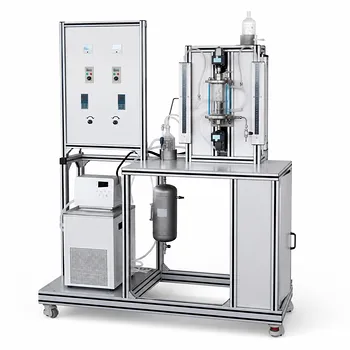
Direct experimental verification turns abstract sizing equations into trusted design tools. Chemical engineering students can utilize gas–liquid separation pilot plants to physically test these relationships. By setting a known gas flow rate ((Q_g)), measuring the actual gas throughput ((Q_a)), and observing separation performance, they can compare real-world efficiency with the predictions of horizontal-vessel length (L = \frac{4 Q_a}{\pi V_t D_v}) and vertical-vessel cross‑sectional area (A = \frac{Q_a}{V_t}). This hands‑on evaluation reveals how vessel geometry and gas velocity truly govern phase separation.
The deepest value of a pilot plant experiment lies not in confirming the textbook equation, but in uncovering when and why the real system deviates from it. Students learn to question idealized assumptions—such as uniform droplet settling or perfect plug flow—and gain the judgment needed to safely size industrial separators.
Why Pilot Plants Are Essential for Verifying Separator Sizing
Pure simulation often misses the multiphase interactions that define separator performance. Running a physical pilot plant bridges the gap between a design formula and the chaotic reality of droplets, mist, and flow maldistribution.
Bridging Theory and Physical Reality
Computer‑based process models can produce clean, idealized results. Real separators, however, experience secondary flow patterns, inlet turbulence, and liquid re‑entrainment that alter separation.
Physical pilot plants expose these non‑idealities directly. A student sees that the calculated cross‑sectional area might be insufficient when the actual gas velocity profile is not flat. That mismatch becomes a powerful lesson in the limits of simple models.
The Specific Equations Under Test
The two most common sizing foundations can be directly validated:
- Horizontal separator length: (L = \frac{4,Q_a}{\pi,V_t,D_v}) — This equation assumes droplets settle from a moving gas stream, relating vessel length to volumetric flow, terminal settling velocity ((V_t)), and vessel diameter ((D_v)).
- Vertical separator cross‑sectional area: (A = \frac{Q_a}{V_t}) — Here the required cross‑section is derived simply from keeping upward gas velocity below the droplet settling velocity.
These formulas are correct in principle, but their coefficients and assumed flow profiles need experimental confirmation. Students who test them on a pilot plant learn that the “right” safety factor depends on the actual droplet size distribution and gas distribution quality.
Designing a Pilot Plant Experiment to Validate Separator Sizing
A well‑structured experimental campaign lets students move from passive formula‑users to critical evaluators. The key is to isolate variables while measuring actual separation efficiency.
Control and Measurement of Gas Flow Rates
Accurate flow control is the foundation. In a pilot‑scale unit, students use mass flow controllers or calibrated rotameters to set (Q_g) and measure the actual gas flow ((Q_a)) downstream of any pressure or temperature compensation.
By observing separation at multiple flow rates, they can determine the maximum throughput before liquid carryover begins. That observed limit can then be compared directly with the theoretical capacity given by the sizing equations.
Varying Geometry and Operating Conditions
A modular pilot plant allows students to change vessel internals, inlet distributors, or even the effective diameter (e.g., by inserting different shell sections). They can:
- Test a vertical column with a fixed area but different height‑to‑diameter ratios.
- Run a horizontal separator with varied weir heights or mist‑extraction devices.
Each variation yields a new set of performance data, showing exactly how the constants and assumptions in the design equation influence real‑world capacity.
Comparing Measured Performance with Theoretical Predictions
The most instructive step is plotting measured separation efficiency (or carryover fraction) against the ratio (Q_a/Q_{\text{design}}). When the real system matches the theoretical curve only up to a certain point, students can identify the threshold where droplet re‑entrainment or liquid level swell causes premature failure.
This side‑by‑side comparison teaches that a sizing equation defines the boundary of safe operation, but not the guarantee of perfect separation.
Understanding the Trade‑offs and Limitations
Pilot plant verification is powerful, but not flawless. Students must confront scale‑down effects and measurement uncertainty to extract trustworthy insights.
Scale‑Down Effects and Ideal Flow Assumptions
Small‑scale pilot plants often exhibit more pronounced wall effects and a narrower range of droplet sizes than an industrial vessel. That can make the simple settling‑law approach fit surprisingly well, giving a false sense of security. Students need to ask whether the droplet size distribution at pilot scale is representative of the full‑scale feed.
Moreover, the horizontal‑vessel length equation assumes plug flow and uniform droplet settling across the entire cross‑section. In a small‑diameter pilot unit, flow may be more uniform than in a large vessel, again hiding real‑world maldistribution.
Instrumentation Accuracy and Data Interpretation
Measuring separation efficiency demands reliable droplet‑size analysis or at least consistent carryover detection. A slightly miscalibrated flow meter can shift the entire validation curve. Students must learn to estimate uncertainty and perform repeat runs, recognizing that a perfect match may be coincidental and that a consistent 10% offset often points to a missing physical factor—such as liquid re‑entrainment—that the formula ignores.
Making the Right Choice for Your Laboratory Goal
How you use the pilot plant should align with what you truly need to learn.
- If your primary focus is understanding the first principles of separator sizing: Run a sequence where you hold all variables constant except gas flow rate and equipment geometry. Plot the theoretical boundary against measured performance and note where and why the two diverge.
- If your primary focus is preparing for an industrial design project: Introduce realistic perturbations—fluctuating inlet flow, foam‑forming liquids, or a wider droplet size distribution—and see how much extra conservatism must be applied to the simple formula to guarantee robust operation.
- If your primary focus is improving process simulation models: Use the pilot plant data to calibrate the terminal settling velocity term ((V_t)) and to develop a correction factor for non‑ideal flow, creating a bridge between pure equation‑of‑state models and field data.
Hands‑on validation turns a one‑line design formula into a trustworthy engineering tool grounded in physical observation.
Summary Table:
| Separator Type | Key Sizing Equation | Experimental Parameters to Measure | Common Real-World Deviations |
|---|---|---|---|
| Horizontal | $L = \frac{4 Q_a}{\pi V_t D_v}$ | Gas flow rate ($Q_g$), vessel length ($L$), droplet settling | Liquid re-entrainment, non-plug flow, turbulence |
| Vertical | $A = \frac{Q_a}{V_t}$ | Cross-sectional area ($A$), gas velocity, terminal velocity ($V_t$) | Inlet velocity maldistribution, droplet size variance |
Bring Hands-On Chemical Engineering to Your Lab
Help your students and researchers bridge the gap between theoretical equations and real-world industrial design. LABPARK provides premium Educational and Vocational Unit Operations Pilot Plants in chemical engineering, bioprocess & biotech, and environmental & water treatment.
Our pilot plants enable universities, research institutes, and enterprises to:
- Validate Sizing Equations: Perform physical experiments to test theoretical design formulas under varying flow rates.
- Analyze Real-World Non-Idealities: Observe inlet turbulence, droplet re-entrainment, and velocity profiles firsthand.
- Enhance Vocational Training: Equip students with the practical skills needed to safely scale up industrial processes.
Ready to elevate your laboratory’s educational and research capabilities? Contact LABPARK today to find the perfect pilot plant configuration for your institution!
Related Products
- Gas-Solid Heterogeneous Separation Demonstration Educational Unit Operations Pilot Plant
- Gallium and Indium Selective Extraction Educational Pilot Plant
- Bench Scale Dual Column Gas Separation and Capture Educational Pilot Plant
- Dual-Drive Stirred Gas-Liquid Mass Transfer Coefficient Determination Pilot Plant
- Packed Bed Absorption Educational Unit Operations Pilot Plant
People Also Ask
- Why is pressure drop characterization critical in separation pilot plants? Key operational insights.
- What are the key thermodynamic considerations for gas mixture modeling? Expert Guide
- What are the primary operational objectives and physical requirements when running heterogeneous separation pilot plants?
- What are the trade-offs in olefin-paraffin separation? Optimize Pilot Plant Performance
- What are the material limitations of gas separation pilot plants? Key factors to consider.