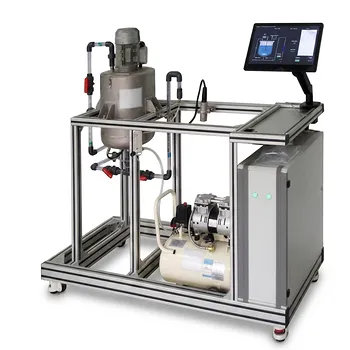
The governing mechanism is the von Kármán rotating-disk boundary layer: viscous shear and the no-slip condition entrain fluid at the disk surface, while centrifugal force drives that fluid radially outward. This radial outflow requires axial replenishment from the surrounding fluid, producing the disk’s inherent pumping or self-circulation action. For the laminar regime, the boundary-layer thickness scales as (\delta \sim \sqrt{\nu/\omega}), so higher rotational speed or lower viscosity produces a thinner, more strongly sheared layer.
Rotating-disk pumping is a coupled viscous–centrifugal process. Viscous entrainment creates circumferential motion, centrifugal force produces radial outflow, and continuity draws fluid axially toward the disk. The same mechanism sets the boundary-layer thickness and strongly influences shear, mixing, and mass transfer.
How the Rotating-Disk Mechanism Works
Viscous entrainment at the disk surface
The fluid touching the disk satisfies the no-slip condition, meaning its velocity matches the disk surface. As the disk rotates, viscous friction transfers angular momentum from the solid surface into the adjacent fluid.
The resulting velocity field is three-dimensional. Fluid has circumferential, radial, and axial velocity components rather than a simple one-directional boundary-layer profile.
Centrifugal radial transport
The rotating fluid experiences a centrifugal acceleration that drives it outward across the disk surface. This creates radial discharge from the disk and establishes the primary pumping component.
The radial movement is not caused by an external pressure-driven pump. It is generated by the disk’s rotation and the momentum transferred through the viscous layer.
Axial replenishment and recirculation
As fluid is expelled radially, continuity requires replacement fluid to move axially toward the disk. This inward axial motion and outward radial motion form a self-sustaining circulation pattern.
In pilot equipment, this mechanism can generate internal recirculation even when no separate circulation pump is installed.
What Sets Boundary-Layer Thickness
Viscosity and rotational speed
The characteristic laminar thickness is governed by the balance between viscous diffusion and rotational motion:
[ \delta \sim \sqrt{\frac{\nu}{\omega}} ]
Here, (\nu) is the fluid’s kinematic viscosity and (\omega) is the disk’s angular velocity.
A commonly used form for the idealized rotating-disk solution is:
[ \delta \approx 5.5\sqrt{\frac{\nu}{\omega}} ]
The numerical coefficient depends on how the boundary-layer thickness is defined, so the scaling relationship is generally more transferable than the coefficient itself.
Rotational Reynolds number
The relevant dimensionless parameter is the rotational Reynolds number:
[ Re_R=\frac{\omega R^2}{\nu} ]
where (R) is the disk radius. Increasing (\omega) or (R), or decreasing (\nu), increases (Re_R) and generally makes inertial effects more important relative to viscous diffusion.
This parameter helps determine whether the flow remains close to the laminar von Kármán state or develops cross-flow instabilities and turbulence.
How the Boundary Layer Produces Pumping
Radial outflow from the disk
For a rotating disk under idealized laminar conditions, the outward radial transport increases with disk size, angular velocity, and the square root of viscosity. A representative one-sided volumetric flux is:
[ Q \approx 0.885\pi R^2\sqrt{\nu\omega} ]
This relation describes the idealized pumping contribution generated by the rotating boundary layer. Actual pilot-scale flow rates also depend on enclosure geometry, clearance, opposing surfaces, feed streams, and whether the disk is fully or partially immersed.
Coupled velocity components
The disk does not simply push fluid outward. Circumferential motion, radial motion, and axial motion are coupled through the rotating boundary-layer equations.
That coupling is why changing rotational speed can alter several process outcomes simultaneously: circulation, wall shear stress, residence-time distribution, heat transfer, and mass transfer.
When the Laminar Model Stops Being Sufficient
Cross-flow instability
The rotating boundary layer is susceptible to cross-flow instability. Centrifugal effects generate secondary motion within the layer, and stationary spiral vortices can develop over an annular region of the disk.
The onset and progression of this instability are commonly described using local rotational Reynolds numbers based on radius. Representative critical values are approximately (1.9\times10^5) for initial instability and (2.8\times10^5) for a completed laminar-to-turbulent transition, although equipment geometry and operating conditions affect the observed thresholds.
Turbulent transport
Once instability or turbulence develops, momentum and mass transport are no longer controlled only by molecular viscosity. Turbulent Reynolds stresses and surface roughness contribute to the velocity profile, torque, wall shear, and energy requirement.
The basic viscous–centrifugal pumping mechanism remains present, but the simple (\sqrt{\nu/\omega}) thickness estimate should then be treated as a laminar reference rather than a complete equipment model.
Understanding the Trade-offs
Higher speed improves transport but raises mechanical demand
Increasing angular velocity thins the boundary layer and increases wall velocity gradients. This can improve mixing and mass transfer, but it also raises wall shear stress, torque, and mechanical power consumption.
At sufficiently high rotational Reynolds numbers, higher speed may also trigger instability or turbulence, producing more complex and less uniform transport behavior.
Lower viscosity thins the layer but changes pumping behavior
A lower-viscosity fluid generally produces a thinner boundary layer and a higher rotational Reynolds number. However, the idealized pumping correlation also shows that the entrained volumetric flux depends on (\sqrt{\nu}), so thinner does not automatically mean lower or higher total circulation in every equipment configuration.
The net process effect must therefore be evaluated using the complete geometry and operating conditions rather than boundary-layer thickness alone.
Idealized correlations have limited scope
The rotating-disk solution assumes a simplified disk, fluid, and flow domain. Real bioprocess and pilot equipment may include finite clearances, baffles, feed and withdrawal streams, multiple disks, non-Newtonian fluids, surface roughness, and heat or mass transfer effects.
These features can change the local velocity field and make direct use of the idealized coefficient inappropriate without validation.
Making the Right Choice for Your Goal
The mechanism provides a useful first model, but pilot-scale design should connect it to the relevant Reynolds number, geometry, and process objective.
- If your primary focus is boundary-layer prediction: Use (\delta \sim \sqrt{\nu/\omega}) as the laminar scaling law, then verify the result against the rotational Reynolds number and the equipment’s actual geometry.
- If your primary focus is pumping and recirculation: Analyze the viscous entrainment, centrifugal radial outflow, and axial replacement flow together; do not model the rotating disk as a purely radial impeller.
- If your primary focus is mixing or mass transfer: Evaluate how disk speed changes wall shear, circulation, and possible cross-flow instability rather than relying on speed alone.
- If your primary focus is scale-up: Match relevant rotational Reynolds numbers and geometric ratios while separately checking torque, power, clearance, and transition behavior.
Understanding the von Kármán rotating-disk boundary layer gives engineers the central physical model for predicting both fluid-layer thickness and rotation-driven pumping in bioprocess and fluid-mechanics pilot equipment.
Summary Table:
| Key factor | Effect on rotating-disk flow | Pilot-equipment significance |
|---|---|---|
| No-slip condition | Transfers angular momentum from the disk to the adjacent fluid | Creates circumferential motion and viscous entrainment |
| Centrifugal force | Drives fluid radially outward across the disk | Produces rotation-driven pumping and circulation |
| Axial replenishment | Draws surrounding fluid toward the disk as fluid exits radially | Sustains self-circulation without a separate pump |
| Viscosity and speed | Laminar thickness follows delta ~ sqrt(nu/omega) |
Higher speed or lower viscosity generally produces a thinner, more strongly sheared layer |
| Rotational Reynolds number | Re_R = omega R^2/nu indicates inertial effects and transition risk |
Helps assess laminar behavior, instability, and turbulence |
| Operating speed | Increases shear, circulation, torque, and power demand | Can improve mixing and mass transfer while increasing mechanical load |
| Equipment geometry | Clearances, baffles, multiple disks, roughness, and non-Newtonian behavior modify flow | Requires validation beyond idealized rotating-disk correlations |
Need to apply rotating-disk flow principles to a real pilot system? Contact LABPARK to discuss your requirements. LABPARK provides Educational and Vocational Unit Operations Pilot Plants for chemical engineering, bioprocess and biotech, and environmental and water treatment applications. Our equipment helps universities, research institutes, and enterprises evaluate circulation, shear, mixing, mass transfer, heat transfer, scale-up conditions, and operating performance using practical pilot-scale systems tailored to your process objectives.
Related Products
- Educational Rotary Disc Liquid-Liquid Extraction Pilot Plant
- High-Gravity Emulsification and Mass Transfer Educational Pilot Plant
- Agitation and Mixing Educational Unit Operations Pilot Plant
- Rising and Falling Film Evaporation Educational Unit Operations Pilot Plant
- Multi-Functional Membrane Separation Educational Pilot Plant for Unit Operations Lab
People Also Ask
- How do density and IFT affect liquid-liquid extraction pilot plants? Optimize Column Performance
- How to Estimate KD for Liquid-Liquid Extraction Pilot Plants Using Henry's Law when Lab Data is Limited
- How to Select a Liquid-Liquid Extraction Pilot Plant with Space Constraints: Key Factors
- In a liquid-liquid extraction pilot plant, how is a ternary-phase diagram utilized to determine solvent feed requirements?
- How to resolve emulsion in liquid-liquid extraction? 5 ways to ensure efficient phase separation