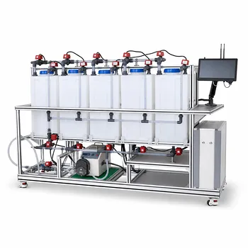
Higher temperature reduces voltage, while controlled osmotic dehydration sharpens selectivity—but push either too far and you lose efficiency.
In a membrane electrolysis pilot plant, raising the operating temperature directly lowers the cell voltage required to drive the reaction, cutting electrical power consumption. At the same time, the high concentrations of anolyte and catholyte create an osmotic pull that partially strips water from the membrane. This dehydration increases the ratio of fixed charged groups to water, improving the membrane’s ability to reject co-ions (permselectivity), but if it becomes excessive, it drives up the membrane’s electrical resistance. The net effect depends entirely on how these two levers are balanced.
The central challenge in pilot‑scale membrane electrolysis is managing the delicate trade‑off: higher temperature saves electricity, osmotic dehydration improves selectivity, but too much dehydration raises resistance and can erase those savings. The art is finding the operating window where these effects reinforce rather than undermine each other.
The Role of Operating Temperature in Electrolysis Efficiency
Temperature is the most direct knob for tuning energy consumption in a membrane electrolysis cell. Because the thermodynamic voltage requirement and kinetic overpotentials both decrease as temperature rises, a warmer cell is inherently more efficient—up to a point.
How Temperature Lowers Cell Voltage
The relationship between temperature and cell voltage is steep and predictable. As the temperature climbs, the reversible cell potential falls, and reaction kinetics speed up, reducing activation overpotentials.
For a perfluorinated membrane system, every increase toward the upper limit of around 90 °C translates into a measurable drop in the total voltage that must be applied to maintain a given current density. This directly lowers the specific energy consumption (kWh per kg of product), which is the dominant operating cost in most pilot‑plant campaigns.
Thermal Limits and Membrane Stability
Perfluorinated membranes tolerate sustained operation near 90 °C, but this is not a universal ceiling. The polymer backbone and its sulfonate functional groups have a thermal stability window that, if exceeded, leads to irreversible loss of ion‑exchange capacity and mechanical softening.
Composite membranes containing polystyrene‑polyethylene structures, in contrast, show pore expansion and a monotonic decline in selectivity when heated to similar temperatures. For a pilot plant running perfluorinated membranes, staying near the high end of the specified range maximizes energy savings while avoiding chemical degradation.
The Conductivity Bonus
A secondary benefit of higher temperature is an increase in membrane ionic conductivity. Ion transport within the membrane follows an Arrhenius‑like activation, so raising the temperature reduces the ohmic drop across the membrane itself. This further lowers the total cell voltage, compounding the thermodynamic gains.
Osmotic Dehydration – A Double‑Edged Sword
Membrane dehydration in an electrolysis stack is not merely a problem to be avoided; it is an intrinsic consequence of the concentration gradient between the anolyte and catholyte loops. Harnessing it correctly improves performance, but loss of control quickly reverses the advantage.
The Mechanism: Anolyte and Catholyte Concentration Gradients
In a typical brine electrolysis pilot plant, the anolyte is a highly concentrated salt solution while the catholyte is a strong caustic solution. The difference in water activity across the membrane generates an osmotic pressure that drives water from the membrane into the more concentrated compartments.
This pulls water out of the membrane’s pores, reducing its internal hydration below the level it would have in equilibrium with pure water. The degree of dehydration is a function of the salt and caustic concentrations, the membrane’s water uptake characteristics, and the local current density.
The Benefit: Enhanced Permselectivity
A partially dehydrated membrane contains a higher local density of sulfonate groups relative to water molecules. Because Donnan exclusion depends on this fixed‑charge concentration, the membrane becomes more effective at blocking the passage of unwanted co‑ions.
The practical result is an improvement in current efficiency: less of the applied current is wasted on side reactions or ion crossover. For pilot‑plant operators aiming to demonstrate high product purity and coulombic efficiency, this mild osmotic dehydration is a desirable operating state.
The Risk: Increased Membrane Resistance
When dehydration passes a critical threshold, the ionic pathways within the membrane become constricted, and the electrical resistance rises sharply. The same Donnan‑effect concentration that improves selectivity now starts to choke ion mobility.
Excessive resistance forces the system to run at a higher voltage to maintain the target current density, directly eating into the energy savings gained from elevated temperature. In severe cases, local hotspots from resistive heating can accelerate membrane degradation, creating a runaway condition.
Understanding the Trade‑offs
Optimizing a membrane electrolysis pilot plant means recognizing that temperature and osmotic dehydration are not independent. They interact through membrane water content, conductivity, and selectivity in ways that produce a narrow “sweet spot” for operation.
The Thermal vs. Electrical Energy Balance
Higher temperature reduces electrical energy demand but may increase the cost of heating the feed streams and maintaining the stack temperature. In plants where waste heat is available (e.g., from a nearby exothermic reaction or a combined heat and power system), the economics tilt strongly toward pushing temperature to the membrane’s stability limit.
When electrical power is cheap and thermal energy is expensive, however, the optimum shifts toward a lower temperature that still achieves acceptable voltage. This balance must be re‑evaluated for every pilot‑plant site and feed‑stock scenario.
Finding the Dehydration Sweet Spot
The ideal osmotic dehydration state is one where the membrane’s water content is just low enough to maximize permselectivity without a large resistance penalty. Operationally, this is tuned by adjusting the anolyte and catholyte concentrations within the recirculation loops.
Monitoring cell voltage at constant current while slowly varying brine and caustic strength reveals the “resistance floor.” As soon as the voltage starts to climb faster than the selectivity gain improves current efficiency, the dehydration has gone too far. That inflection point marks the practical optimum.
When Membrane Material Matters
Perfluorinated membranes exhibit a wide stable hydration window, making them forgiving of osmotic swings. If the pilot plant must explore novel membrane chemistries—such as hydrocarbon‑based or composite structures—extra care is required, because pore swelling and selectivity loss at elevated temperature can overlap with dehydration‑induced resistance and permanently degrade separation performance.
How to Apply This to Your Pilot Plant
The right operating strategy depends on whether your primary goal is demonstrating low energy consumption, proving high product purity, or establishing the robustness of the process for scale‑up. The guidelines below translate the science into actionable choices.
- If your primary focus is minimizing electrical energy cost: Operate at the highest temperature the membrane can tolerate (near 90 °C for perfluorinated materials) and accept modest osmotic dehydration, while monitoring resistance for any sharp increase.
- If your primary focus is maximizing product purity and current efficiency: Use controlled osmotic dehydration by maintaining high anolyte and catholyte concentrations, but keep the temperature sufficiently high to keep membrane resistance low—never sacrifice so much conductivity that voltage penalties erase the selectivity gains.
- If your primary focus is long‑term membrane durability and stable baseline data: Avoid the extreme ends of both levers; run at a moderate temperature (70–80 °C) and moderate concentration gradients, ensuring that dehydration never pushes resistance above a 10–15% increase from the fully hydrated baseline.
Mastering the interplay of temperature and osmotic dehydration is what turns a membrane electrolysis pilot plant from a black box into a well‑tuned instrument, delivering efficiency data that can be trusted at commercial scale.
Summary Table:
| Parameter | Positive Impact | Negative Impact / Risk | Optimal Strategy |
|---|---|---|---|
| Operating Temp | Lowers cell voltage, boosts ionic conductivity | Thermal degradation, loss of membrane stability | Run at maximum safe limit (e.g., 90°C for perfluorinated) |
| Osmotic Dehydration | Enhances permselectivity (better rejection) | Drastically increases membrane electrical resistance | Control concentrations to stay just below resistance inflection point |
Optimize Your Chemical Engineering & Bioprocess Workflows with LABPARK
Are you looking to scale your membrane electrolysis processes or upgrade your research lab? LABPARK provides premium Educational and Vocational Unit Operations Pilot Plants in chemical engineering, bioprocess & biotech, and environmental & water treatment designed for universities, research institutes, and enterprises.
Why Partner with LABPARK?
- Academic & Industrial Reliability: Train students and researchers on industry-standard pilot equipment.
- Precision Control: Achieve the exact operating temperatures and concentration gradients needed for accurate data.
- Custom Engineering: Tailored setups to match your specific research objectives.
Take the next step in process scaling and education—contact LABPARK today to discuss your project!
Related Products
- Alkaline Membrane Water Electrolysis Educational Pilot Plant Unit Operations Training System
- Electrolytic Hydrogen Production Educational Unit Operations Pilot Plant
- Multi Functional Membrane Crystallization Educational Unit Operations Pilot Plant
- Electrolyte Distillation Purification and Formulation Educational Pilot Plant
- Ultrafiltration Membrane Separation Educational Pilot Plant
People Also Ask
- How do chemical engineering pilot plants demonstrate electrolysis? Bridge Theory & Industrial Scale
- How do composite membranes affect NaOH production? Key factors for high current efficiency.
- What are the core parameters of water electrolysis efficiency? Master them with pilot plants.
- Gap-Electrode vs. Zero-Gap Membrane: Key Design Choices for Water Electrolysis Pilot Plants
- How do alkaline and PEM electrolysis technologies differ in pilot plant operations?