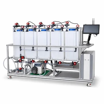
The definitive starting point for any electrodialysis (ED) fouling control strategy is to operate the stack below its limiting current density (LCD). This single parameter directly prevents water splitting, the primary trigger for catastrophic inorganic scaling. For organic and colloidal fouling, researchers can then physically shake foulants loose by periodically reversing the electrical polarity of the stack, a technique known as electrodialysis reversal (EDR). Finally, for stubborn organic fractions, applying a charged surface modification to the membrane can electrostatically repel the foulants away.
The fight against membrane fouling in an ED pilot plant is a battle for experimental consistency. Your core objective isn't just cleaning; it's preventing the electrochemical disruption of your feed stream. Maintaining a current below the limiting threshold is the non-negotiable first step, while polarity reversal and surface modification serve as layered defenses to ensure your separation data remains repeatable and reliable.
Understanding the Fouling Battlefield in Electrodialysis
Unlike pressure-driven filtration, ED systems face fouling driven by electrical potential. The core challenge is that the membrane itself becomes the site for chemical reactions that trigger precipitation.
The Limiting Current: Your First Line of Defense Against Scaling
Inorganic scaling, particularly from calcium carbonate, doesn't just happen because salts are present. It happens because the operating current fundamentally changes the water chemistry at the membrane surface.
When you exceed the limiting current density (LCD), a phenomenon called water splitting occurs. In this state, water molecules at the ion-depleted boundary layer split into H⁺ and OH⁻ ions to carry the current. This localized production of hydroxide ions spikes the pH inside the concentration chamber.
This high-pH micro-environment forces dissolved calcium to precipitate directly onto the membrane. The result is a dense, impermeable scale that rapidly destroys membrane conductivity. By setting a hard operational ceiling at approximately 80% of the experimentally determined LCD, you prevent the pH instability that causes nucleation.
Electrodialysis Reversal: Physical Scouring of Loose Deposits
Even with perfect current control, colloidal particles and early-stage organic films can deposit loosely on the membrane surface. This is where the dynamic nature of EDR provides a massive advantage.
By periodically reversing the electrical polarity, you swap the hydraulic function of the channels. The former concentrating chambers become the diluting channels, forcing the feed flow to shear off any accumulated foulants that are not yet chemically bonded. This prevents the maturation of a fouling layer, effectively acting as a continuous, in-situ hydraulic wash without requiring chemical intervention or system shutdown.
Controlling Organic Fouling Through Electrostatics
For dissolved organic compounds that naturally carry a charge, physical rinsing may not be enough. These substances often adsorb strongly to the ion exchange membrane surfaces via electrostatic attraction.
A targeted strategy involves modifying the membrane surface with a thin film carrying the same charge as the dominant foulants. If your feed contains negatively charged organics, a weakly negative coating creates a repulsive barrier. This prevents the initial attachment without significantly impeding the transport of target ions. It’s a proactive, preventive measure that builds fouling resistance directly into the material science of the pilot plant setup.
Enhancing Stability Through Fluid Dynamics and System Integration
Beyond the electrochemical controls, the physical operation of the pilot plant critically impacts how long your membranes last during a research campaign.
Mitigating Concentration Polarization
Concentration polarization is distinct from fouling but is often its precursor. It’s a steep ion concentration gradient near the membrane surface that increases electrical resistance and lowers the effective LCD.
Faster flow velocities are the most direct cure. By increasing the crossflow rate on the diluting side, you thin the stagnant boundary layer. Integrating turbulence promoters or spacers within the narrow membrane channels further disrupts this layer, dramatically improving ion back-diffusion and preventing the localized starvation that leads to water splitting. Higher operating temperatures also aid this process by increasing ion mobility.
Preventing Structural Failure in Pilot Operations
In educational and research settings, equipment often sits idle between experiments. This downtime poses a silent risk that has nothing to do with the feed water chemistry.
Fouling control is irrelevant if the polymer matrix cracks. Ion exchange membranes swell when hydrated. If researchers leave membranes to dry out completely after a run, the polymer contracts and structural fissures inevitably form. Detecting these micro-cracks is difficult, often leading to unexplained cross-leakage and poor selectivity in the next experiment. Proper shutdown protocols mandate wet storage to maintain the osmotic equilibrium of the fixed ions within the membrane structure.
Understanding the Trade-offs
Effective mitigation requires an objective view of where these methods fall short in a research context.
EDR introduces operational complexity and data noise. Reversing polarity periodically disrupts the steady-state condition, causing a momentary spike in the product water stream’s conductivity. For a student trying to model steady-state mass transfer, these cyclical disturbances introduce a layer of data filtering that complicates analysis.
Membrane modification trades raw throughput for resilience. An anti-fouling coating, while blocking organics, adds a resistance layer that often requires a slightly higher operational voltage to maintain the same ionic flux. This slightly increases the specific energy consumption per unit of salt removed.
Chemical cleaning remains a last resort that resets the baseline. Inevitably, baseline performance will decline. When physical EDR and operational controls aren't enough, a chemical cleaning protocol using acids to dissolve scale or high-concentration salt solutions to disrupt organic binding is required. However, this always leaves the researcher questioning whether the membrane selectivity was restored to its original state, introducing a variable into long-term studies.
Making the Right Choice for Your Research Goal
The precise combination of these mitigation strategies depends entirely on your experimental objective.
- If your primary focus is accurate salt transport modeling: Prioritize stable electrochemical conditions. Set a hard current limit well below the LCD and implement a rigorous wet-storage protocol, minimizing the noise variables introduced by EDR cycling.
- If your primary focus is robustness testing of wastewater: EDR is your indispensable tool. Combine aggressive polarity reversal schedules with high linear flow velocities to physically reject the raw colloidal load, accepting the cyclical data variance as an inherent system property.
- If your primary focus is clean-in-place (CIP) protocol development: Document the baseline separation performance meticulously. Then systematically test the most common aggressive foulants, using the reversible EDR process as a control variable against the permanent efficiency gains of targeted chemical or enzymatic cleaning cycles.
Proper fouling control in ED is the art of maintaining a stable chemical and electrochemical environment. By dominating the limiting current, you prevent the problem; by reversing the polarity, you manage it; and by storing membranes wet, you safeguard the foundation that makes all of it possible.
Summary Table:
| Strategy | Mechanism | Key Advantage | Major Trade-off |
|---|---|---|---|
| Operate Below LCD | Prevents water splitting and localized pH spikes | Stops inorganic scaling nucleation | Limits maximum ionic throughput |
| Polarity Reversal (EDR) | Periodically swaps hydraulic channel functions | Shears off loose deposits in-situ | Disrupts steady-state data analysis |
| Surface Modification | Introduces repulsive electrostatic charges | Prevents organic adsorption | Increases overall electrical resistance |
| High Flow Velocity | Thins the stagnant boundary layer | Minimizes concentration polarization | Increases pumping energy consumption |
| Wet Storage Protocol | Keeps polymer matrix swollen and stable | Prevents membrane cracking and leaks | Requires strict operational discipline |
Optimize Your Water Treatment Research with LABPARK
Are you looking to elevate your research or hands-on training? LABPARK provides state-of-the-art Educational and Vocational Unit Operations Pilot Plants in chemical engineering, bioprocess & biotech, and environmental & water treatment. Specifically designed for universities, research institutes, and enterprises, our systems ensure experimental consistency and reliable scaling data.
Take the next step in advancing your laboratory capabilities—contact LABPARK today to discuss your project requirements!
Related Products
- Electrochemical Water Treatment Educational Unit Operations Pilot Plant
- Water Electrolysis Hydrogen Production and Storage Educational Pilot Plant
- Electrolytic Hydrogen Production Educational Unit Operations Pilot Plant
- Alkaline Membrane Water Electrolysis Educational Pilot Plant Unit Operations Training System
- Electrolyte Distillation Purification and Formulation Educational Pilot Plant
People Also Ask
- What design features do educational electrochemical pilot plants utilize to manage gas liberation and water loss?
- How can unit operations pilot plants show lead-acid concentration vs state of charge? Real-time monitoring guide.
- How do educational electrochemical pilot plants scale up electrolysis? Master industrial engineering.
- How to Estimate Sulfate in Water Treatment Pilot Plant Deposits: Gravimetric Guide
- How can foaming be managed during steam generation experiments in water treatment unit operations pilot plants? Tips