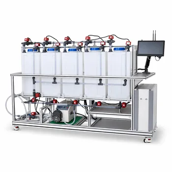
Solid-liquid washing and recycle loops are integrated as a continuous polishing step around the ice separator. In a freeze-desalination pilot plant, seawater is cooled until relatively pure ice crystals form in a concentrated brine slurry, then a mechanical skimmer or separator removes the ice. A small fraction of the melted product water, commonly about 5%, is recycled to wash the separated ice bed, displacing salt-rich brine before the ice is melted into the final product stream.
The recycle loop improves product purity by replacing retained surface brine with low-salinity meltwater. Its design must balance washing effectiveness against the loss of product water and the added hydraulic load on pumps, separators, and melters.
How the Freeze-Desalination Circuit Is Organized
Cooling and crystallization create the solid-liquid mixture
The feed seawater enters a cooling or crystallizing unit, where water freezes preferentially as ice crystals. Dissolved salts remain mainly in the unfrozen liquid, producing a concentrated brine slurry.
The crystallizer therefore does not produce a clean solid and a clean liquid. It produces ice containing or carrying some brine, which makes the downstream solid-liquid separation step critical.
Mechanical separation harvests the ice
A mechanical skimmer, slusher, screen, or comparable separator removes the ice crystals from the brine-rich slurry. The separated brine stream is withdrawn from the process so that its increasing salt concentration does not contaminate the product loop.
The harvested ice still retains a thin film or pockets of concentrated brine. This retained liquid is the main source of residual salt in the melted product.
The melter produces the product-water stream
After washing, the ice is transferred to a melting unit. The resulting liquid is collected as desalinated product water, while the brine and wash effluent are directed away from the clean product outlet.
The process boundary should distinguish the washed ice, final product water, recycled wash water, and purge brine. Treating these as separate streams makes the unit operation easier to analyze and control.
How the Solid-Liquid Washing Loop Works
A portion of product water is diverted
The product-water line is split after melting. Most of the meltwater leaves as usable product, while a small fraction is pumped back to the ice separator.
A representative pilot-plant configuration recycles approximately 5% of the melted pure product water. The exact value is an operating variable rather than a universal design requirement.
Recycled water displaces retained brine
The recycled water is distributed across the ice bed or through the skimmer so it contacts the crystal surfaces. Because it contains far less salt than the retained brine, it displaces and dilutes the salt-laden liquid film.
The wash effluent is kept separate from the clean product stream and is normally combined with the concentrated brine discharge or another reject stream.
Washing is integrated with separation
The wash step is not a separate batch operation performed after the pilot plant has stopped. It is integrated into continuous solids handling, allowing ice removal, washing, and melting to occur in sequence.
This arrangement enables operators to study washing efficiency, salt rejection, and the interaction between mechanical separation and liquid displacement under steady operating conditions.
Why Recycle Is Needed
Retained brine determines residual product salinity
If the ice retains a brine weight fraction of β, and that brine has a salt concentration σ, the salt concentration in the melted ice product can be approximated as:
ε = σ × β
Here, ε represents the salt concentration introduced by the retained liquid. Even a small retained-liquid fraction can create substantial product salinity when the brine is highly concentrated.
Washing reduces the liquid carried with the solid
The recycle loop targets β, the amount of brine physically carried with the ice. Reducing this value lowers the salt transferred into the melter and improves the purity of the final water.
For example, reducing retained brine from 1.0 wt% to 0.5 wt% materially reduces salt loading from the solid phase. The actual potable-water recovery improvement depends on the crystallizer yield, brine concentration, wash-water demand, and product specification.
The loop demonstrates non-ideal separation
An ideal separator would send dry ice to the melter and all brine to the reject stream. A pilot plant must instead model the real behavior of wet crystals, including entrained and surface-adhering liquid.
This makes the system useful for teaching component balances across the crystallizer, separator, washing zone, and melter.
How to Model the Recycle
Define the system boundary
A practical balance should include the cooling or crystallizing unit, mechanical separator, wash section, melter, product outlet, recycle line, and brine purge.
The balance must track both total water and salt. It should also identify whether the wash stream is counted as product, reject, or internal circulation.
Account for the recycled flow
If the melter produces a total meltwater flow M and a fraction f is recycled, then:
- Recycle flow:
fM - Net product flow before other losses:
(1 - f)M
For a representative 5% recycle, f = 0.05. The loop therefore returns 0.05M to the separator and leaves approximately 0.95M as net product before accounting for purge and operating losses.
Include the brine purge
The recycle loop cannot operate indefinitely without removing salt and accumulated reject liquid. The displaced brine must leave through a controlled reject or purge stream.
Without an adequate purge, salt can circulate within the system and progressively increase the salinity of the wash water, reducing its effectiveness.
Size equipment for total circulation
Pumps, piping, spray or distribution devices, holding tanks, and the separator must handle the internal recycle flow in addition to the net product flow.
The recycle rate can also affect residence time, hydraulic loading, ice-bed depth, and the capacity required in the brine-handling system.
Controlling the Pilot-Plant Operation
Control the wash rate
The wash-water flow should be measured and adjusted independently from the main product flow. Operators can vary the recycle fraction to determine how product salinity changes with wash intensity.
A flow meter, control valve, and sampling point are sufficient for a basic educational system; research systems may add conductivity or salinity measurement on the wash effluent and final product.
Distribute water evenly across the ice
Poor distribution can create unwetted regions where brine remains attached to the crystals. The wash system should therefore spread water across the ice bed rather than discharge it at a single point.
The separator geometry, ice depth, crystal size, and contact time all influence how effectively the recycled water displaces retained brine.
Monitor product and reject quality
Product conductivity or salt concentration indicates whether the washing step is meeting its target. Reject salinity helps reveal whether the purge is removing the displaced brine effectively.
Mass-balance closure should also be checked by comparing feed water and salt with product, reject, and internal recycle streams.
Understanding the Trade-offs
More washing improves purity but consumes product water
Increasing the recycle fraction generally provides more wash capacity and can reduce salt transfer from the ice. However, every unit of water sent back to the separator is temporarily unavailable as net product.
The optimum recycle rate is the lowest rate that achieves the required product salinity and stable operation.
Recycle increases hydraulic and mechanical load
Internal circulation raises the flow handled by pumps, pipes, separators, and tanks. Excessive flow can disturb the ice bed, increase splashing or entrainment, and make separation less effective.
Pilot equipment should therefore be sized for total process circulation, not only the desired net water-production rate.
Washing does not replace good crystallization and separation
A wash loop cannot fully compensate for poorly controlled freezing, excessive brine entrainment, or an overloaded separator. Crystal size, slurry concentration, drainage time, and separator performance remain important.
The best design combines controlled crystallization with effective solids drainage and a measured washing step.
Recycled water can become contaminated
If the recycle takeoff is placed downstream of an inadequately separated or contaminated stream, salt can be returned to the ice bed instead of removed from it. The recycle point should be located on the clean side of the melter, with a clear separation between product water and reject streams.
A purge and periodic quality checks are necessary to prevent contaminant accumulation.
Making the Right Choice for Your Goal
Use the loop as an experimental design variable, not as a fixed operating assumption.
- If your primary focus is product purity: Increase or optimize the wash-water contact with the ice, monitor final salinity, and reduce retained brine before increasing the total recycle rate.
- If your primary focus is water recovery: Minimize the recycle fraction while maintaining the required salt specification, because recycled product water reduces net output.
- If your primary focus is mass-balance education: Define every stream around the crystallizer, separator, washer, melter, purge, and recycle line, then track water and salt independently.
- If your primary focus is continuous pilot operation: Provide controlled flow distribution, a brine purge, sampling points, and equipment capacity for both forward and recycled flows.
A well-designed freeze-desalination pilot plant treats washing and recycling as an integrated mass-transfer and separation problem, allowing product purity, recovery, and equipment limits to be optimized together.
Summary Table:
| Process Element | Function | Key Design Consideration |
|---|---|---|
| Crystallizer | Freezes water into ice while concentrating salts in brine | Control crystal size, slurry concentration, and freezing conditions |
| Mechanical separator | Removes ice from the brine-rich slurry | Minimize brine carryover and retain effective drainage |
| Recycle wash loop | Uses low-salinity meltwater to displace brine from ice surfaces | Optimize the recycle fraction, commonly around 5% of meltwater |
| Melter | Converts washed ice into product water | Keep washed ice, product water, recycle, and reject streams separate |
| Brine purge | Removes displaced brine and accumulated salts | Maintain purge capacity to prevent salt buildup in the recycle loop |
| Monitoring and control | Tracks flow, conductivity, salinity, and mass-balance closure | Measure wash rate and product quality under steady operation |
| Main trade-off | Higher washing improves purity but reduces net product flow | Use the lowest recycle rate that meets the product specification |
Optimize Your Freeze-Desalination Pilot Plant
Need to evaluate ice washing, salt rejection, water recovery, or continuous recycle performance? Contact LABPARK to discuss an Educational or Vocational Unit Operations Pilot Plant tailored to your needs.
LABPARK supports universities, research institutes, and enterprises with pilot plants for chemical engineering, bioprocess and biotechnology, and environmental and water-treatment studies. Our systems help you investigate crystallization, solid-liquid separation, washing efficiency, brine purging, recycle control, hydraulic loading, and product-quality performance in one integrated platform. Contact us to develop a practical pilot-plant configuration for teaching, research, process development, or operator training.
Related Products
- Electrochemical Water Treatment Educational Unit Operations Pilot Plant
- Multi-Functional Special Distillation Educational Pilot Plant
- Continuous Batch Extractive Distillation Educational Pilot Plant
- Green Anhydrous Ethanol Purification Extractive Distillation Unit Operations Training Pilot Plant
- Electrolyte Distillation Purification and Formulation Educational Pilot Plant
People Also Ask
- What design features do educational electrochemical pilot plants utilize to manage gas liberation and water loss?
- How can unit operations pilot plants show lead-acid concentration vs state of charge? Real-time monitoring guide.
- How do educational electrochemical pilot plants scale up electrolysis? Master industrial engineering.
- How to Estimate Sulfate in Water Treatment Pilot Plant Deposits: Gravimetric Guide
- How can foaming be managed during steam generation experiments in water treatment unit operations pilot plants? Tips