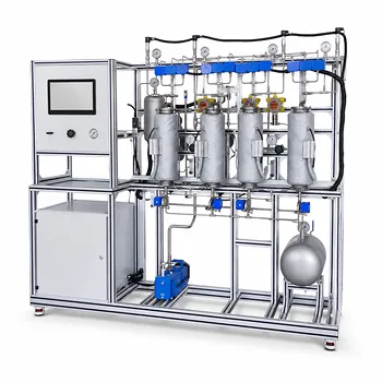
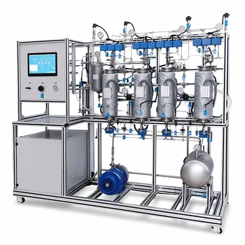
To study carbon dioxide (CO2) flooding and oil displacement mechanisms, at the core of any chemical engineering pilot plant you need a high-pressure core flooding rig and a dedicated PVT (Pressure-Volume-Temperature) analysis system. The core flooding apparatus directly measures how much extra oil is produced when CO2 is injected into a porous rock sample, while the PVT setup reveals exactly how the CO2 physically alters the crude oil – causing it to swell, thin out, and vaporize light components. Together, these two equipment families recreate the deep-reservoir conditions that turn CO2 into a supercritical, liquid-like solvent, letting researchers precisely quantify recovery efficiency and optimize injection pressure.
A core flooding rig gives you the “what” – how much oil is displaced – but the PVT cell gives you the “why” – the solubility, swelling, and viscosity changes that make CO2 flooding work. The most instructive pilot plants integrate both to link microscopic phase behavior to macroscopic displacement performance, all while carefully managing the high pressures and safety systems required.
The Core Flooding Pilot System: Simulating a Reservoir in the Lab
This is the workhorse for direct oil displacement experiments. It’s essentially a miniature reservoir compressed into a stainless steel assembly, where you can control everything from rock type to flow rate.
What the Setup Includes
A typical academic or research core flooding system bundles a high-pressure injection pump (for CO2 and brine), a robust core holder that can take confining pressures up to several thousand psi, a back-pressure regulator to maintain reservoir conditions on the outlet, and a precise effluent collection system. Temperature-controlled ovens or heating jackets wrap around the core holder to replicate downhole heat, often around 170°F. Pressure transducers and differential pressure gauges log the flood in real time, while a fraction collector or in-line separator measures oil, water, and gas production.
Simulating Real Reservoir Conditions
The system forces CO2 through either consolidated core samples like limestone or sandstone, or through unconsolidated sand packs. By applying an overburden pressure via a confining sleeve, the rock feels the same stress it would thousands of feet underground. This prevents artificial bypass and ensures the displacement reflects true reservoir flow paths. The ability to replicate both vertical and horizontal flooding lets you study gravity override and gas fingering – two field-scale challenges that directly affect how much oil gets left behind.
Measuring Recovery and Optimum Pressure
The primary output of a core flood is a plot of oil recovery versus hydrocarbon pore volume injected (HCPVI). You steadily increase the injection pressure until you cross the minimum miscibility pressure (MMP), where CO2 and oil become a single phase. The pilot plant hardware lets you precisely identify that optimum operating window, because once miscibility is achieved, the recovery jumps dramatically and the residual oil saturation drops to a fraction of its original value. Data from these runs feed directly into field-scale project economics.
The PVT Apparatus: Unlocking CO2–Oil Phase Behavior
Before you ever push CO2 through a core, you need to understand how the gas and oil interact at a molecular level. This is where the PVT cell comes in.
Measuring Solubility and Density Matching
A high-pressure PVT cell – essentially a transparent, piston-equipped sapphire or steel cylinder – lets you mix CO2 and crude oil at precise temperatures and pressures. Under typical reservoir conditions like 2,000 psia, CO2 solubility can reach 65 mol percent. The PVT experiment visualizes this: as the gas dissolves, the oil phase expands, and the density difference between the CO2 and the oil shrinks. That density matching is the mechanism that prevents gravity override, keeping the CO2 from simply riding the top of the reservoir. Pilot plants teach this by letting you tilt the cell and watch the phases settle – or, more often, not settle at all.
Quantifying Volumetric Swelling
Dissolved CO2 physically forces the oil molecules apart. In a PVT run, you measure the swelling factor – the ratio of oil volume after CO2 dissolution to its original volume. A 65‑mol‑percent CO2 mixture can swell the oil by up to 25%. That swelling directly displaces bypassed oil, pushing it out of dead-end pores and toward production wells even before the injected front arrives. The pilot plant typically records this change via a laser or camera-based level detection, giving a direct visual of the mechanism.
Measuring Viscosity Reduction
A parallel experiment – often using a capillary viscometer integrated into the PVT circuit – tracks how the oil’s resistance to flow plummets. Dissolved CO2 can cut crude oil viscosity by up to 100‑fold, transforming a tar-like substance into something that flows almost like kerosene. This dramatically improves the mobility ratio, meaning the injected CO2 no longer outruns the oil through high-permeability streaks. In practice, this eliminates gas fingering and ensures a more uniform sweep. The PVT setup quantifies this change, giving you the rheological data you need to feed into reservoir simulators.
Infrastructure and Safety: The Unseen Requirements
Pilot plants operate at dangerous pressures and temperatures. Neglecting the plant utilities is the fastest way to get bad data – or a serious accident.
Utility Requirements for High-Pressure Operation
Before installing any core flood or PVT system, you must verify that the lab’s electricity, cooling water, and ventilation match the equipment’s design basis. High-pressure syringe pumps often require three‑phase power and dedicated circuits. The cooling water loop (typically at 10–15°C) maintains seal integrity in the core holder and pre‑conditions the injected fluids. For steam-based heating systems, the steam pressure and condensate return must be adequate. Overlooking a simple parameter like cooling water temperature can cause premature pump seal failure or erratic back‑pressure regulation, corrupting the measured recovery curve.
Safe Ventilation and Drainage
CO2 is heavier than air and can accumulate in low spots, creating an asphyxiation hazard. All pilot units must be housed in well‑ventilated areas with CO2 gas sensors tied to automatic shut‑off valves. Drainage must safely handle hydrocarbon effluents – the separator produces small amounts of crude oil and brine that cannot be poured down a standard sink. A chemical-resistant, fire-rated drain line with a sump is the bare minimum. These infrastructure points are not optional; they are part of the experimental setup and must be scoped before equipment procurement.
Understanding the Trade-offs
While laboratory-grade pilot plants deliver unparalleled insight, they come with real constraints that researchers and educators must accept.
Complexity versus Educational Value
A fully instrumented core flooding system with automated fraction collection can be intimidating. Students can spend more time debugging software and chasing leaks than actually learning the EOR mechanisms. Simplified, manually operated PVT cells – where you literally crank a piston and observe phase changes – often provide a deeper intuitive grasp of CO2‑oil interactions. Prioritize transparency and tactile control if your primary goal is teaching, and save the automation for high‑throughput research.
Safety Concerns and Operational Costs
Every additional transducer or automated valve adds a potential leak path. At 3,000 psi, a failed fitting can become a projectile. The consumable costs (gaskets, sleeve seals, filter cartridges) and the price of high‑purity CO2 also add up quickly. And while supercritical CO2 can, in other applications, replace toxic solvents and reduce VOC emissions by up to 80%, a core flood still handles flammable crude oil – so fire suppression and explosion‑proof equipment may be required. A thorough hazard and operability (HAZOP) review is a must before any run.
Making the Right Choice for Your Goal
Your specific research or educational objective determines which equipment to prioritize and how to configure it. Use these goal-driven guidelines to focus your setup.
- If your primary focus is demonstrating fundamental EOR mechanisms: Start with a high‑pressure PVT cell and visual swelling/viscosity measurements. This directly shows solubility, density matching, swelling, and viscosity reduction in a way that’s easy to understand and requires less auxiliary infrastructure.
- If your primary focus is measuring oil recovery and optimizing injection pressure: Invest in a robust core flooding system with accurate pressure control and fraction collection. This setup produces the recovery‑vs.‑HCPVI data that engineers need to design a field pilot, even if you pair it with a basic auxiliary PVT unit for context.
- If your primary focus is linking microscopic phase behavior to macroscopic sweep: Integrate both a PVT system and a core flooder, then use the PVT-generated fluid properties to interpret the core flood displacement patterns. This combination is essential for advanced research into miscible‑gas EOR and for training engineers who will scale lab results to field forecasts.
With the right combination of equipment – and the respect for safety and infrastructure it demands – a pilot plant becomes a powerful, tangible teacher of the principles that drive today’s CO2-enhanced oil recovery.
Summary Table:
| Equipment | Core Function | Key Parameters Measured |
|---|---|---|
| Core Flooding Rig | Simulates fluid displacement in porous reservoir rock. | Oil recovery vs. HCPVI, minimum miscibility pressure (MMP), sweep efficiency. |
| PVT Apparatus | Analyzes thermodynamic phase behavior of CO2-oil mixtures. | CO2 solubility, volumetric swelling factor, viscosity reduction. |
| Support & Safety Systems | Maintains operating conditions and ensures laboratory safety. | System pressure, temperature control, CO2 gas detection, waste drainage. |
Ready to Equip Your Chemical Engineering Lab?
LABPARK provides high-quality Educational and Vocational Unit Operations Pilot Plants in chemical engineering, bioprocess & biotech, and environmental & water treatment. Designed specifically for universities, research institutes, and enterprises, our systems deliver the safety, reliability, and precision needed for advanced EOR research and hands-on vocational training.
Contact LABPARK today to discuss your laboratory requirements and receive a customized technical proposal!
Related Products
- Two Phase Flow Pattern Velocity Resistance Measurement Educational Pilot Plant
- Carbon Dioxide PVT Curve Determination Educational Unit Operations Pilot Plant
- Carbon Dioxide Adsorption and Capture Educational Unit Operations Pilot Plant
- Carbon Dioxide Capture and Utilization Educational Pilot Plant for Unit Operations
- Carbon Dioxide Absorption and Desorption Educational Pilot Plant for Carbon Capture Studies
People Also Ask
- How to update chemometric calibration models in pilot plants? Best practices for process engineers.
- Why is continuous measurement preferred over manual sampling in pilot plants? Get real-time kinetic insights.
- Why is Peng-Robinson preferred over SRK? Enhance thermodynamic modeling in educational pilot plants.
- How does gas velocity affect static elevation pressure drop? Master the Flanigan Method
- What limits the homogeneous flow liquid ratio in pilot plants, and how is it addressed?