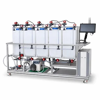
Direct-contact triple-point freezing uses water itself as the refrigerant, replacing the indirect heat-exchange loop found in conventional freeze-desalination pilot plants. Under vacuum, saline feed is cooled while water vaporizes directly from the brine, producing ice crystals and concentrated brine. The vapor is compressed and routed to a melter/condenser, where its condensation supplies the latent heat needed to melt the separated ice into fresh water.
The central advantage is process integration: the same water that is removed from the saline feed provides the refrigerant vapor and the heat source for ice melting. This eliminates much of the secondary-refrigerant circuit while improving direct-contact heat transfer and reducing equipment complexity.
How the Two Process Configurations Work
Direct-contact triple-point operation
In a direct-contact system, seawater enters a low-pressure freezer or slusher operating near the phase-equilibrium region where ice, concentrated brine, and water vapor coexist.
Pressure reduction causes a portion of the water to evaporate. The latent heat required for this evaporation comes directly from the saline feed, lowering its temperature until part of the water crystallizes as ice.
The process is often described as operating at the “triple point of seawater,” but this wording requires care. Seawater is a multicomponent solution, so its equilibrium conditions differ from the pure-water triple point; in practice, the system operates near a controlled ice-brine-vapor equilibrium at low pressure.
Vapor compression and ice melting
The generated water vapor is withdrawn from the freezer and compressed. Compression raises its pressure and saturation temperature sufficiently for it to condense in the melter.
Separated ice crystals are brought into contact with the condensing vapor. The vapor releases its latent heat, melting the ice and producing a low-salinity water product.
This arrangement couples the freezing and melting duties through one working fluid: water vapor. The vapor is not merely a by-product; it is the internal heat-transfer medium linking both modules.
Conventional secondary-refrigerant operation
A conventional pilot plant uses a separate refrigeration circuit, commonly based on a refrigerant such as ammonia or, historically, chlorofluorocarbons. That refrigerant circulates through a compressor, condenser, expansion device, and evaporator.
The saline feed is cooled indirectly through a heat exchanger. The refrigerant remains isolated from the seawater by exchanger walls and associated piping.
Ice melting may use heat recovered from the refrigeration system or a separate loop. The result is a more clearly separated process, but it requires additional thermal interfaces and equipment.
Key Process Advantages
Lower equipment count and simpler construction
Direct contact removes the need for internal heat-exchange surfaces between the refrigerant and the saline stream. The pilot plant can therefore avoid much of the piping, exchanger surface, containment, and refrigerant-management equipment required by an indirect system.
This can reduce capital cost, mechanical complexity, and assembly effort, which is particularly valuable in laboratory and teaching-scale equipment.
More effective heat transfer
Direct contact between water vapor and brine avoids the thermal resistance imposed by exchanger walls, fouling layers, and stagnant boundary films.
The result is a more intimate transfer of latent heat between phases. In principle, this allows a smaller temperature difference to drive the process and makes the freezer and melter more thermally integrated than an indirect shell-and-tube arrangement.
Integrated use of latent heat
The system uses vapor compression to transfer heat from the freezing step to the melting step. Water vapor generated during evaporation becomes the heating medium after compression.
This provides a direct framework for studying latent-heat recovery, compressor work, and overall energy balance. The pilot plant can show how refrigeration work affects the net energy required per unit of freshwater produced.
Reduced dependence on foreign refrigerants
Water is the process refrigerant, so the plant does not need a charge of ammonia, a halocarbon, or another external refrigerant for the primary freezing duty.
That reduces concerns associated with refrigerant toxicity, flammability, ozone depletion, or environmental release. The safety benefit is especially relevant in instructional laboratories, vocational facilities, and demonstration plants.
Clearer observation of phase-equilibrium behavior
Because freezing occurs through direct vaporization and crystallization, the pilot plant provides a practical platform for observing multiphase equilibrium.
Students and researchers can evaluate how pressure, temperature, salinity, and vapor removal affect ice formation and brine concentration. These observations connect thermodynamic theory to measurable unit-operation behavior.
Fewer indirect thermal bottlenecks
In a secondary loop, performance depends on multiple interfaces: refrigerant-to-wall transfer, wall conduction, wall-to-brine transfer, and often additional heat-transfer steps in the melter.
Direct contact removes several of these resistances. The dominant limitations shift toward vapor generation, phase separation, compression, ice handling, and control of the vacuum system.
Operating Principles That Govern Performance
Maintain the correct pressure-temperature relationship
The freezer pressure must be low enough to support water evaporation and the desired freezing temperature. Pressure, temperature, and brine salinity must be controlled together because increasing salinity changes the equilibrium conditions for ice formation.
The system should therefore be treated as a controlled multiphase equilibrium operation, not simply as a conventional refrigeration evaporator operated at lower pressure.
Control ice crystal formation and separation
The objective is to form ice with low entrained brine and then separate it from the concentrated liquid. Crystal size, slurry concentration, residence time, and hydrodynamic mixing all affect product quality and downstream handling.
Poor separation can carry concentrated brine into the melter, reducing freshwater purity. Excessively fine crystals can also increase separation difficulty and raise the risk of solids accumulation.
Protect vapor quality
The vapor line and compressor should receive predominantly water vapor rather than liquid droplets, brine aerosols, or ice particles. Carryover can cause corrosion, contamination, erosion, or mechanical damage.
Demisters, suitable disengagement volume, and controlled vapor velocities may be required even though the process avoids a separate refrigerant loop.
Use compression to match freezing and melting duties
The compressor must raise the vapor pressure and saturation temperature enough to melt the separated ice. Its operating point determines the balance between heat-transfer driving force and electrical energy consumption.
A higher condensing temperature can make melting easier but may increase compressor work. Pilot testing should measure both the recovered melting duty and the compression energy required to provide it.
Track the complete material and energy balance
A valid pilot-plant analysis should account for feed salinity, ice production, brine rejection, vapor flow, freshwater recovery, compressor power, vacuum-system duty, and heat losses.
Enthalpy changes across the freezer, compressor, and melter are central measurements. Focusing only on freezer temperature or freshwater flow can conceal energy penalties elsewhere in the system.
Understanding the Trade-offs
Direct contact does not eliminate all complexity
Removing the secondary refrigerant loop simplifies one part of the plant, but the system still requires a vacuum vessel, vapor compressor, phase separators, ice-handling equipment, and process controls.
The complexity is relocated toward multiphase flow management and vapor compression. The design is simpler thermally, but not necessarily simple mechanically.
Product contamination remains a process risk
Water vapor is intended to be clean, but droplets of concentrated brine can be entrained in the vapor stream. If that carryover reaches the melter, the final water quality can deteriorate.
Direct contact therefore requires effective vapor-liquid disengagement and verification of product salinity. The absence of a foreign refrigerant does not remove the need for contamination control.
Vacuum operation imposes equipment and control demands
Low-pressure operation requires vessels and piping designed for external pressure. Leaks, air ingress, noncondensable gases, and unstable pressure control can reduce evaporation and impair vapor condensation.
Pilot plants must monitor absolute pressure and noncondensable accumulation rather than relying only on temperature readings.
Compression energy can dominate the balance
The direct-contact concept improves heat transfer and enables heat recovery, but the vapor compressor still consumes substantial energy. The net benefit depends on compression ratio, pressure levels, heat losses, throughput, and the effectiveness of ice melting.
A claim of superior thermal efficiency should therefore be demonstrated through a measured system energy balance, not inferred solely from the absence of heat-exchanger walls.
Brine concentration limits recovery
As ice forms, salts remain primarily in the liquid phase, increasing brine concentration. This can depress the freezing temperature, alter phase behavior, increase viscosity, and eventually limit further ice production.
Brine management and controlled withdrawal are necessary to prevent the freezer from drifting away from its intended operating condition.
Why the Difference Matters in Pilot Plants
Better demonstration of integrated unit operations
A direct-contact plant links evaporation, crystallization, phase separation, vapor compression, and condensation in one visible process sequence.
That makes it useful for teaching how unit operations interact rather than treating refrigeration, crystallization, and melting as isolated steps.
More meaningful energy-efficiency experiments
The configuration allows researchers to vary pressure, compressor conditions, ice production rate, and melter performance while observing their effect on total energy use.
It is particularly suitable for studying whether latent heat recovered through vapor compression offsets the added electrical work of compression.
More accessible laboratory operation
Eliminating hazardous or environmentally problematic refrigerants can simplify laboratory safety procedures and reduce the consequences of leaks.
However, vacuum safety, rotating machinery, hot or cold surfaces, brine handling, and electrical hazards still require formal controls and operating procedures.
Making the Right Choice for Your Goal
The appropriate configuration depends on whether the pilot plant is intended primarily to demonstrate process integration, compare energy performance, or provide a robust reference system.
- If your primary focus is process simplicity and educational accessibility: Use direct-contact freezing to demonstrate water-vapor refrigeration, ice formation, vapor compression, and ice melting with fewer refrigerant-side components.
- If your primary focus is maximum heat-transfer integration: Use direct contact to minimize wall and fouling resistances, while carefully controlling vapor-liquid separation.
- If your primary focus is experimental energy analysis: Instrument both the compressor and the vacuum system, then compare recovered melting duty against total electrical consumption.
- If your primary focus is operational robustness and refrigerant isolation: A secondary-refrigerant loop may offer clearer separation between the refrigeration circuit and saline process, despite higher equipment count and indirect heat-transfer losses.
- If your primary focus is freshwater quality: Prioritize crystal washing or separation, vapor demisting, brine control, and product-salinity measurement regardless of the refrigeration architecture.
Direct-contact triple-point freezing is most valuable when its reduced refrigerant-loop complexity is matched by disciplined control of vacuum conditions, phase separation, compression energy, and brine concentration.
Summary Table:
| Aspect | Direct-contact triple-point freezing | Secondary-refrigerant loop |
|---|---|---|
| Refrigerant | Water vapor generated from the saline feed | Separate refrigerant such as ammonia or a halocarbon |
| Heat transfer | Direct vapor-brine and vapor-ice contact | Indirect transfer through heat-exchanger walls |
| Main advantages | Lower equipment count, integrated latent-heat recovery, and fewer thermal resistances | Clear separation between refrigerant and saline process streams |
| Key equipment | Vacuum freezer, vapor compressor, phase separator, ice handler, and melter | Compressor, condenser, expansion device, evaporator, heat exchangers, and associated piping |
| Primary control needs | Vacuum pressure, salinity, ice crystals, vapor quality, compression, and brine concentration | Refrigerant conditions, heat-exchanger performance, feed temperature, and ice formation |
| Main risks | Brine carryover, air ingress, noncondensables, compressor energy, and difficult ice separation | Fouling, exchanger losses, refrigerant handling, and greater mechanical complexity |
| Best pilot-plant use | Demonstrating integrated evaporation, crystallization, vapor compression, and melting | Studying isolated refrigeration performance and robust refrigerant-process separation |
| Critical measurements | Freshwater salinity, ice and brine flow, vapor flow, pressure, temperature, compressor power, and vacuum duty | Refrigerant flow, temperatures, pressures, heat duties, and electrical consumption |
Are you planning a desalination pilot plant for teaching, research, or process development? Contact LABPARK to discuss an Educational or Vocational Unit Operations Pilot Plant tailored to your goals. LABPARK provides pilot plants for chemical engineering, bioprocess and biotechnology, and environmental and water-treatment applications. Our systems help universities, research institutes, and enterprises evaluate vacuum operation, ice crystallization, phase separation, vapor compression, latent-heat recovery, brine concentration, freshwater quality, and complete energy balances in a controlled, practical environment. We can help you select the right direct-contact or secondary-refrigerant configuration, define instrumentation and safety requirements, and build a reliable platform for hands-on training, experimental research, and process scale-up.
Related Products
- Multi-Modal Distillation Unit Operations Training Pilot Plant
- Electrochemical Water Treatment Educational Unit Operations Pilot Plant
- Multimodal Absorption and Desorption Pilot Plant for Unit Operations Training
- Multi-Functional Drying Educational Unit Operations Pilot Plant
- Multi-Reactor Educational Pilot Plant for Reaction Engineering Unit Operations
People Also Ask
- How can energy balance equations for condensers & reboilers be validated experimentally? Guide
- How do distillation pilot plants validate VLE data? Achieve reliable solvent separation scale-up.
- Why is vacuum operation capability an essential feature for a distillation unit operations pilot plant? Unlock Efficiency
- How can real-time carbon number prediction improve distillation pilot plants? Optimize control.
- How does thermodynamic model selection affect pressure-sensitive azeotropic distillation pilot plants? Design with validated VLE