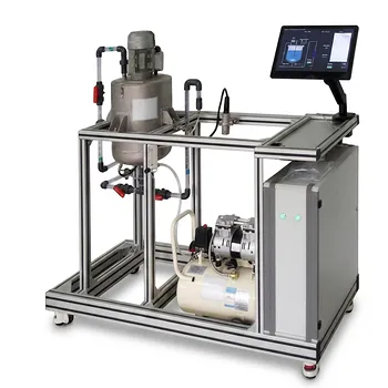
Field instruments and control panel components are interconnected through three main transmission paths: capillary, electrical, and pneumatic. A sensing element detects a process condition and communicates it either through a fluid-filled capillary line or an electrical signal to a panel indicator, controller, or alarm. The control system then sends an output—often through a pneumatic connection—to the final control element, such as a pressure control valve.
The complete connection is a measurement-and-action loop: the field instrument senses the process, the panel device interprets or displays the signal, and the control device actuates the process equipment through an appropriate output connection.
How the Instrumentation Loop Is Organized
The field instrument measures the process
Field instruments begin with a primary sensing element that responds to a process variable such as temperature, pressure, or level.
Depending on the instrument design, the sensing element may connect directly to a transmitter, alarm, or control system through a capillary line or electrical wiring.
The control panel receives and processes information
Panel-mounted devices such as Temperature Indicator Controllers (TICs) and alarm panels receive signals from the field.
These devices may display the measured value, compare it with a desired operating condition, generate an alarm, or determine the required corrective action.
The final control element changes the process
A control output is sent to a device such as a Pressure Control Valve (PCV).
The valve responds by changing the process flow or pressure, closing the loop between measurement and physical process control.
How Capillary Lines Interconnect Instruments
Direct fluid-filled transmission
A capillary line is a small, fluid-filled connection between a sensing element and a remote instrument.
The process condition is transmitted through the behavior of the fluid inside the line rather than through an electrical conductor.
Typical applications
Capillary lines can connect temperature sensing elements to field transmitters.
They may also connect sensing elements directly to panel-mounted alarms, such as a high-level alarm, when the instrument arrangement is designed for direct indication or alarm action.
What this means for the control system
With a capillary connection, the sensing function is transmitted mechanically or hydraulically to the receiving instrument.
The panel device then provides the indication or alarm function; the capillary itself does not act as a general-purpose control signal.
How Electrical Signals Interconnect Field and Panel Devices
Transmitters send process information
Field transmitters convert a measured process condition into an electrical signal.
That signal travels to a control-room panel device, such as a temperature indicator controller or a low-pressure alarm panel.
Panel devices interpret the signal
The receiving controller or alarm panel uses the electrical signal to represent the measured process variable.
A controller can use that information to determine whether corrective action is needed, while an alarm panel can identify an abnormal condition such as low pressure.
Electrical connections support centralized control
Electrical signaling allows field measurements to be brought together at a control panel.
This makes it possible for operators or automatic controllers to monitor process conditions without being physically located at each sensor.
How Pneumatic Lines Actuate Control Valves
Compressed air provides the actuating force
Pneumatic lines use compressed air to connect control devices with valve stems or valve actuators.
The air provides the mechanical force required to move the valve.
Pneumatic control of a PCV
For a pressure control application, the control system determines the required valve response and sends the appropriate pneumatic output to the pressure control valve.
The valve stem moves, changing the valve position and thereby influencing the controlled process condition.
Pneumatic lines are different from measurement lines
A pneumatic connection generally performs the final control action rather than carrying the original sensor measurement.
In simplified form, the measurement travels from the field instrument to the panel electrically or through a capillary line, while compressed air transmits the actuation force to the valve.
The Complete Signal Path
Measurement path
A typical measurement path is:
Process condition → sensing element → transmitter or alarm device → electrical or capillary connection → control panel
For example, a temperature sensing element may connect to a transmitter, which then sends an electrical signal to a TIC.
Decision path
The panel device receives the measurement and determines the required response.
For control applications, the controller evaluates the process condition against the intended operating condition and produces a control output.
Actuation path
The final path is:
Control output → pneumatic line → valve actuator or stem → process adjustment
For a pressure-control loop, this action moves the PCV to influence the process pressure.
Understanding the Trade-offs
Capillary connections can simplify direct sensing
Capillary lines provide a direct connection between a sensing element and a remote instrument or alarm.
However, they are limited to applications where the sensing arrangement and installation distance are suitable for fluid-filled transmission.
Electrical signals centralize monitoring
Electrical connections make it practical to transmit measurements from field transmitters to centralized controllers and alarm panels.
Their effectiveness depends on having compatible field instruments, panel devices, and signal wiring.
Pneumatic actuation supplies force but requires air
Pneumatic connections are well suited to operating valve stems because compressed air supplies mechanical force.
They also require an appropriate compressed-air source and correctly configured control devices; the pneumatic line is therefore part of the final control system, not merely an information display path.
Similar-looking connections may serve different functions
A common mistake is to treat every instrument connection as carrying the same type of signal.
Capillary lines transmit sensing effects, electrical lines transmit measurement or control information, and pneumatic lines primarily transmit actuating force to the final control element.
How to Apply This to Your Process Unit
The correct way to understand an interconnected control unit is to trace each loop from the sensor, through the panel device, to the final control element.
- If your primary focus is measurement: Identify whether the sensing element reaches the receiving instrument through a capillary line or through a transmitter and electrical signal.
- If your primary focus is operator monitoring: Trace the electrical or capillary connection to the relevant indicator, controller, or alarm panel.
- If your primary focus is automatic control: Follow the controller’s output to the pneumatic line and then to the valve actuator or stem.
- If your primary focus is troubleshooting: Separate the loop into sensing, signal transmission, panel processing, and final actuation sections before diagnosing the fault.
Understanding these distinct connection paths turns a collection of instruments and panels into a clear, traceable process-control loop.
Summary Table:
| Connection type | Primary function | Typical connection path | Main requirement |
|---|---|---|---|
| Capillary | Transmits a sensing effect through fluid-filled tubing | Sensing element to remote indicator or alarm | Suitable installation distance and sensing arrangement |
| Electrical | Transmits measured data or control signals | Field transmitter to TIC, controller, or alarm panel | Compatible instruments, signal wiring, and power |
| Pneumatic | Provides actuating force for final control | Controller output to valve actuator or stem | Reliable compressed-air supply and correct configuration |
| Complete loop | Measures, processes, and adjusts the process | Sensor to panel device to PCV or other final control element | Correctly connected and traceable control loop |
Connect Your Process-Control System with LABPARK
Need a clear, reliable process-control setup for teaching, research, or production? Contact LABPARK to discuss your requirements. LABPARK provides Educational and Vocational Unit Operations Pilot Plants covering chemical engineering, bioprocess and biotech, and environmental and water treatment. Our systems help universities, research institutes, and enterprises integrate field instruments, control panels, transmitters, alarms, pneumatic valves, and complete measurement-and-action loops for practical training, process development, and technical demonstration.
Related Products
- Multimodal Absorption and Desorption Pilot Plant for Unit Operations Training
- Multi Pump Fluid Transport Process Piping Unit Operations Training Pilot Plant
- Multi-Functional Membrane Separation Educational Pilot Plant for Unit Operations Lab
- Multi-Functional Drying Educational Unit Operations Pilot Plant
- Chemical Pipeline Assembly and Fluid Transport Practical Training Unit Operations Pilot Plant
People Also Ask
- How do predictive thermodynamic models integrate into pilot plants? Bridging Theory and Practice
- Which cross-validation strategy should be selected for pilot plant time-series & batch data? Avoid Data Leakage
- How do utility requirements influence pilot plant selection? Avoid Costly Lab Integration Mistakes
- Why Use Center Points in Process Analyzer Calibration? Key Benefits Explained
- How can process control schemes be configured to teach basic and advanced control?