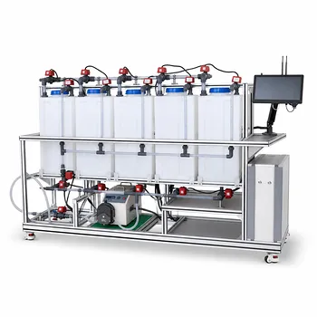
In an educational chemical engineering pilot plant, the incompressible continuity equation, (\nabla \cdot \mathbf{v}=0), means that fluid volume is conserved locally: flow does not accumulate or disappear within a control volume. For steady liquid flow through a pipe network, this becomes (Q=uA=\text{constant}) along a pipe section, allowing students to relate flowmeter readings, pipe velocities, and pressure measurements without modeling density changes.
For water and dilute liquid solutions, (\nabla \cdot \mathbf{v}=0) is a powerful modeling simplification: the volumetric flow entering a steady control volume must equal the volumetric flow leaving it. The equation supports flowmeter calibration, velocity prediction at diameter changes, hydraulic balances, and experimental validation of Bernoulli’s equation.
What the Equation Means Physically
Local Conservation of Volume
The general continuity equation is
[ \frac{\partial \rho}{\partial t}+\nabla \cdot (\rho \mathbf{v})=0 ]
where (\rho) is density and (\mathbf{v}) is the velocity field.
For a fluid with constant density, this reduces to
[ \nabla \cdot \mathbf{v}=0 ]
The equation does not mean that velocity is identical everywhere. It means that the net volumetric expansion of the velocity field is zero: fluid entering a small region must be balanced by fluid leaving it.
From Velocity Fields to Flow Rate
For one-dimensional, steady flow through a pipe,
[ Q=uA ]
where (Q) is volumetric flow rate, (u) is average velocity, and (A) is cross-sectional area.
For an incompressible fluid with no side stream, leak, or accumulation,
[ u_1A_1=u_2A_2 ]
This is the form students most often use when analyzing pilot-plant piping.
Pipe Diameter Changes Matter
For a circular pipe,
[ A=\frac{\pi d^2}{4} ]
Therefore,
[ \frac{u_2}{u_1}=\left(\frac{d_1}{d_2}\right)^2 ]
If a branch pipe has half the diameter of a main pipe, its average velocity is four times greater for the same volumetric flow rate. That change affects local pressure, shear, erosion risk, mixing behavior, and the interpretation of sensor data.
How Continuity Supports Flow Measurement
Calibrating Rotameters and Magnetic Flowmeters
Pilot plants commonly use rotameters, magnetic flowmeters, Venturi meters, or orifice plates to measure flow. For a steady incompressible liquid system, a known flow rate measured at one location provides a reference for checking another meter downstream.
A practical calibration exercise is therefore based on
[ Q_{\text{in}} \approx Q_{\text{out}} ]
after accounting for measurement uncertainty, branch flows, and any intentional discharge.
Interpreting Differential-Pressure Devices
Venturi meters and orifice plates infer flow from pressure differences caused by changes in velocity. Continuity supplies the velocity relationship, while Bernoulli’s equation connects velocity changes to pressure-head changes.
For example, a reduced cross-section produces a higher local velocity. Under appropriate assumptions, the corresponding pressure decrease can be compared with measurements from pressure taps installed before and after the restriction.
Building a Measurement Balance
A useful pilot-plant balance is
[ Q_{\text{in}}-\sum Q_{\text{out}}=\frac{dV}{dt} ]
At steady state, (dV/dt=0), so
[ Q_{\text{in}}=\sum Q_{\text{out}} ]
This form is more reliable than assuming that every meter in a complex network must display the same value. Flow rates remain equal only along sections without branches, leaks, storage, or other sources and sinks.
How Continuity Supports Process Modeling
Liquid Transport Systems
For water and dilute solutions, density changes caused by ordinary pressure variations are usually negligible. Engineers can therefore write hydraulic balances directly in terms of volumetric flow rate.
This simplifies calculations for pumps, valves, pipe sections, fittings, and distribution headers. Students can focus on how geometry and equipment resistance affect flow while treating density as constant.
Filtration and Fluidized-Bed Experiments
Continuity helps establish the superficial velocity through a filter or packed bed:
[ u_s=\frac{Q}{A} ]
The superficial velocity can then be related to pressure drop, filtration behavior, or fluidization conditions. Continuity alone does not predict the pressure drop; it supplies the flow variable required by the relevant hydraulic correlation.
Heat-Exchange Loops
In a single-phase liquid heat-exchange loop, the mass flow rate is approximately constant:
[ \dot{m}=\rho Q ]
If (\rho) is treated as constant, constant mass flow and constant volumetric flow are equivalent. This allows students to combine continuity with an energy balance to determine heat-transfer rates and temperature changes.
Hydraulic Network Balances
At a junction, continuity provides the central equation:
[ \sum Q_{\text{in}}=\sum Q_{\text{out}} ]
Additional equations are needed to determine the individual branch flows. These may include pump curves, valve characteristics, friction-loss equations, and pressure-drop correlations.
Continuity is therefore the conservation constraint within a larger process model, not a complete model of the plant by itself.
Connecting Theory to Pilot-Plant Data
Comparing Meter Locations
Students can measure flow at different points in a piping loop and compare readings with the continuity prediction. Differences may result from meter calibration, installation effects, pulsating pump operation, trapped air, unsteady tank levels, or unrecognized branch flows.
The comparison teaches an important engineering lesson: conservation laws predict the expected balance, while instruments reveal how closely the real system achieves or measures that balance.
Validating Bernoulli’s Equation
A typical experiment changes the flow rate through a pipe containing different diameters or fittings. Students calculate velocity from (Q/A), estimate pressure-head changes, and compare the result with pressure-transducer measurements.
The ideal Bernoulli equation must generally be extended with pump work, friction losses, and fitting losses:
[ \frac{P_1}{\rho g}+\frac{u_1^2}{2g}+z_1+h_p
\frac{P_2}{\rho g}+\frac{u_2^2}{2g}+z_2+h_L ]
Continuity supplies the velocity terms; it does not eliminate energy losses.
Diagnosing Experimental Problems
A continuity imbalance can help identify process faults. Possible causes include a leaking valve, a partially blocked line, an incorrectly ranged flowmeter, liquid accumulation in a vessel, or a sensor installed where the flow profile is disturbed.
This makes the equation useful not only for teaching theory but also for developing plant-monitoring and troubleshooting skills.
When the Simplification Is Appropriate
Water and Dilute Liquid Solutions
The incompressible approximation is usually appropriate for water and dilute liquid solutions in ordinary educational piping, filtration, and heat-transfer experiments. Pressure and temperature changes may alter density slightly, but often not enough to justify a variable-density model for the learning objective.
The approximation should still be checked when operating conditions involve large temperature changes, high pressures, significant concentration changes, or strongly nonideal solutions.
Low-Pressure-Drop Gas Flow
Gas flow can sometimes be treated as incompressible when the pressure drop is a very small fraction of the absolute inlet pressure and the velocity is far below the speed of sound. A low Mach number alone is not a universal guarantee of constant density; pressure and temperature changes must also remain sufficiently small.
For gas systems, density should be estimated at a representative pressure and temperature only when that approximation is justified.
Continuum-Scale Equipment
The equation assumes that the fluid can be modeled as a continuum. This is normally valid in pilot-plant pipes, tanks, filters, and heat exchangers because the equipment dimensions are enormously larger than molecular mean free paths.
At conventional pilot-plant scales, molecular discreteness does not normally require a kinetic rather than continuum description.
Understanding the Trade-offs
Constant Density Does Not Mean Constant Velocity
Velocity changes whenever the cross-sectional area changes. A divergence-free field can therefore contain acceleration and deceleration, provided the local volume balance remains satisfied.
Confusing (\nabla\cdot\mathbf{v}=0) with uniform velocity leads to incorrect predictions at reducers, nozzles, branches, and measurement devices.
Steady Flow Is a Separate Assumption
The equation (\nabla\cdot\mathbf{v}=0) expresses incompressibility, not necessarily steady operation. A liquid system can be incompressible but unsteady when a tank is filling, a pump is cycling, or a valve is being adjusted.
For transient systems, the control-volume balance must retain the accumulation term (dV/dt).
Branches and Storage Break Simple “Same Flow Everywhere” Reasoning
Flow rate is not necessarily constant throughout an entire pilot plant. At a junction, the inlet flow divides among branches, and in a tank or vessel the difference between inlet and outlet flow changes the stored volume.
A correct model applies continuity to each relevant control volume and includes every inlet, outlet, and accumulation term.
Variable-Density Thermal Flow Requires Care
In thermal convection, density can vary with temperature and drive buoyancy. Under a low-speed Boussinesq approximation, the velocity field is often treated as divergence-free while density variation is retained in the buoyancy term, but this is an approximation with a defined range of validity.
For substantial heating, evaporation, mixing of different concentrations, or multiphase operation, a variable-density continuity equation is more appropriate.
Compressible Gas Flow May Need a Full Model
When a gas experiences a substantial pressure drop, its density changes as it expands. The model must then account for pressure, temperature, and possibly nonideal-gas behavior through an equation of state such as
[ Pv=Z\frac{RT}{M} ]
where (Z) is the compressibility factor and (M) is molecular mass.
In such cases, treating (Q) as constant can be misleading because mass flow may remain constant while volumetric flow changes along the pipe.
Applying the Equation in a Pilot Plant
A disciplined workflow keeps the simplified model useful without applying it beyond its limits.
- Define the control volume and identify every inlet, outlet, branch, leak, and storage volume.
- Decide whether the fluid density can reasonably be treated as constant over the pressure, temperature, and concentration range.
- Determine whether the system is at steady state.
- Use (Q=uA) to calculate average velocities in each uniform pipe section.
- Apply junction and control-volume balances before using pressure-drop or energy equations.
- Compare predicted flow balances with calibrated instrument readings and quantify measurement uncertainty.
- Replace the incompressible model with a variable-density or compressible model when the operating conditions require it.
Making the Right Choice for Your Goal
Use the equation according to the process question you are trying to answer.
- If your primary focus is flowmeter calibration: Use steady liquid continuity to compare readings at locations without branches or accumulation, while treating meter uncertainty and installation effects explicitly.
- If your primary focus is pipe sizing or velocity prediction: Use (u=Q/A) to evaluate diameter changes, then assess the resulting pressure loss, shear, erosion, and equipment limits.
- If your primary focus is filtration or fluidized-bed operation: Calculate superficial velocity from (Q/A), then combine it with the appropriate pressure-drop or fluidization correlation.
- If your primary focus is heat-exchanger performance: Use continuity to establish mass flow, then combine it with an energy balance and measured inlet and outlet temperatures.
- If your primary focus is gas transport: Verify that pressure and temperature changes are small enough for the incompressible approximation before using a constant-density model.
- If your primary focus is transient operation: Retain the accumulation term and model changes in vessel volume rather than assuming equal inlet and outlet flow.
Used with clearly stated assumptions, (\nabla\cdot\mathbf{v}=0) turns pilot-plant measurements into defensible flow balances and connects classroom conservation laws to real process behavior.
Summary Table:
| Application | Continuity principle | Practical learning outcome |
|---|---|---|
| Flow measurement | Q = uA; Qin = Qout at steady state | Compare and calibrate flowmeter readings |
| Pipe diameter changes | u1A1 = u2A2 | Predict velocity and assess pressure effects |
| Branch networks | Sum Qin = Sum Qout | Balance flow at junctions and identify abnormal readings |
| Filtration and fluidized beds | Superficial velocity us = Q/A | Connect flow rate with pressure drop and fluidization behavior |
| Heat-exchange loops | Mass flow m-dot = rhoQ | Combine flow continuity with energy balances |
| Troubleshooting | Imbalance indicates leaks, storage, blockage, or instrument error | Diagnose pilot-plant and measurement problems |
| Model selection | Constant density is suitable only within defined operating limits | Recognize when variable-density or compressible models are required |
Build Better Pilot-Plant Learning and Process Models
Connect theory with reliable experimental data using LABPARK Educational and Vocational Unit Operations Pilot Plants. Our systems support practical instruction and applied research in chemical engineering, bioprocess and biotech, and environmental and water treatment.
LABPARK helps universities, research institutes, and enterprises evaluate flow measurement, hydraulic balances, filtration, fluidized beds, heat exchange, pipe networks, and process-control performance in realistic operating conditions. Our pilot plants enable students and engineers to validate continuity and Bernoulli models, quantify measurement uncertainty, troubleshoot equipment, and develop stronger process-design skills.
Contact LABPARK to discuss a pilot-plant configuration that matches your teaching, research, training, or industrial process-development goals.
Related Products
- Multi-Reactor Educational Pilot Plant for Reaction Engineering Unit Operations
- Fixed Bed Gas Solid Catalytic Reaction Educational Pilot Plant
- Multi-Functional Special Distillation Educational Pilot Plant
- Fixed-Bed Chemical Reaction and Gas Dust Tar Removal Unit Operations Pilot Plant
- Carbon Dioxide Hydrogen Methanol Synthesis Educational Unit Operations Pilot Plant
People Also Ask
- How do reactor pilot plants define QbD design space? Master chemical process scale-up.
- When configuring a reactor unit operations pilot plant for highly exothermic reactions, how to prevent thermal runaway?
- How do metal ion-catalyzed reaction mechanisms inform chemical engineering pilot plant design? From kinetics to scale-up
- What are the barriers to process intensification & how do pilot plants help?
- What role do educational pilot plants play in scaling green chemistry? Bridging the Lab-to-Industry Gap