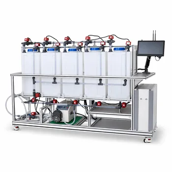
The limiting current density in an electrodialysis pilot plant is not a fixed value—it is a dynamic parameter that scales directly with the flow velocity of the feed solution. As the fluid travels through the membrane stack, its velocity controls the thickness of the stagnant diffusion boundary layer clinging to the membrane surface. A higher velocity thins this layer, accelerating ion transport to the membrane and raising the limit at which concentration polarization sets in, often captured by the empirical relationship i_lim = A vⁿ, where n falls between 1/3 and 1/2. This makes flow velocity the primary operational dial for pushing performance without destroying the membranes or wasting energy.
The surface question is about a formula, but the deeper need is ensuring a pilot plant runs safely, efficiently, and predictably. Flow velocity is the master variable that prevents the system from tipping past the limiting current density—a threshold beyond which concentration polarization triggers water-splitting, irreversible membrane damage, hazardous gas generation, and a sharp drop in current efficiency. Designing the hydraulic path and local velocities is therefore just as critical as selecting the membranes themselves.
The Physics: How Flow Velocity Governs Limiting Current Density
The Diffusion Boundary Layer and Mass Transport
In an electrodialysis cell, ions must migrate from the bulk solution through a thin, low-flow region right at the membrane surface. This is the diffusion boundary layer.
At low flow velocities, the boundary layer thickens, slowing the rate of ion replenishment. The membrane consumes ions faster than they can be resupplied, causing the salt concentration at the interface to plummet.
The Empirical Relationship: i_lim = A vⁿ
For most pilot-scale stacks, the limiting current density follows a power-law dependence on the linear velocity v. The exponent n depends on the flow regime and spacer geometry.
- Laminar-like conditions typically yield n ≈ 1/3.
- Turbulent or spacer-enhanced mixing pushes n closer to 1/2.
This relationship gives engineers a direct control knob: increase pump speed or adjust channel geometry, and i_lim rises, allowing higher productive current densities without crossing the safety threshold.
Why Exceeding the Limit Triggers a Cascade of Problems
When the applied current density surpasses i_lim, the ion concentration at the membrane face effectively drops to zero. The electrical resistance of the depleted layer skyrockets.
The voltage then shifts to support secondary reactions. In water-based feeds, this means water-splitting—the unwanted electrolysis of water into H⁺ and OH⁻ ions. These ions can precipitate foulants, chemically attack ion-exchange groups, and permanently degrade membrane selectivity. In environmental treatment units removing dilute metals, excess current also drives side reactions like hydrogen and oxygen gas evolution, which creates safety hazards and erodes faradaic efficiency.
Why This Relationship is Critical for Pilot Plant Design
Protecting Membranes from Irreversible Damage
Operating above i_lim for extended periods is one of the fastest ways to destroy a pilot stack. The localized pH swings caused by water-splitting can delaminate ion-exchange membranes or cause permanent scaling.
A design that guarantees sufficient flow velocity everywhere—even at the stack's furthest corners—is the only insurance against this. This is where flow distribution, not just average velocity, becomes paramount.
Ensuring Energy Efficiency and Process Safety
Once water-splitting begins, every additional volt applied to the stack goes into driving this parasitic reaction instead of desalting the feed. Current efficiency plummets, and the power bill climbs for no productivity gain.
From a safety standpoint, pilot plants treating waste streams can accumulate explosive hydrogen concentrations inside the stack if the system inadvertently crosses the limiting current. Maintaining flow above the critical design velocity keeps the cell potential in the safe, target-reaction zone.
Flow Configuration as a Design Lever
How the incoming stream is distributed across the individual membrane chambers directly determines the local velocities and pressure profiles.
In a successive (series) flow arrangement, desalting speed increases, but pressure differences from chamber to chamber can become severe. This uneven pressure loading often deforms or tears membranes.
Counterflow configurations reduce diffusion transport and boost current efficiency, yet they also introduce high pressure differentials across the stack. In practice, pilot-scale electrodialysis adopts a middle ground: a parallel flow system within a single stack to equalize pressure, combined with a counterflow sequence between multiple stacks to maximize energy efficiency and protect the membranes from mechanical damage.
Understanding the Trade-offs
Higher Velocity Means Higher Pumping Costs
While increasing flow velocity raises i_lim, it also demands more pumping power. The pressure drop through the narrow spacer-filled channels grows with the square of velocity, and the pilot plant’s energy balance must account for both the stack power and the hydraulic circuit.
The optimum design velocity is rarely the maximum physically possible; it is the one that minimizes total specific energy consumption—the sum of electrical energy for ion transfer and hydraulic energy for circulation.
Pressure Drop Limitations and Membrane Distortion
Pilot stacks have a maximum allowable transmembrane pressure before the thin polymer membranes begin to bulge into the concentrate channel or tear. Even if a higher velocity would boost i_lim, the associated pressure rise can mechanically damage the stack.
This forces a design envelope where the chosen flow path must deliver the required i_lim without exceeding the safe differential pressure limit of the specific membrane grade used.
Flow Maldistribution Can Create Localized Limiting Current Issues
A single number for average velocity glosses over reality. If the inlet manifold feeds some channels briskly and others barely at all, the sluggish compartments will experience concentration polarization far earlier than expected—even when the global i_lim calculation says the process is safe.
Good pilot design therefore pairs the velocity target with flow-equalization strategies, such as properly sized distribution troughs and careful gasket porting, to keep all membrane sections operating in the safe, sub-limiting regime.
Making the Right Choice for Your Pilot Plant
Your optimal approach depends on the primary goal the pilot plant is meant to prove or achieve. Use the following guidelines to anchor your design decisions.
- If your primary focus is maximizing desalination throughput: Push for the highest practical velocity your membranes and spacers can tolerate without mechanical damage. Supplement with turbulent spacer designs that steepen the i_lim-versus-velocity curve (higher n), and invest in careful manifold engineering to avoid flow starvation.
- If your primary focus is membrane longevity and low-maintenance operation: Select a conservative design velocity well above the predicted i_lim with a healthy safety factor, and prioritize a parallel flow distribution within the stack to equalize pressure. Never allow the system to approach the limiting current at the lowest anticipated feed conductivity.
- If your primary focus is energy efficiency and process control: Map out the complete energy curve—stack DC power plus pumping power—and operate at the velocity that delivers the lowest specific energy consumption. This often means running closer to i_lim but under stringent voltage monitoring to prevent accidental water-splitting events.
A well-characterized pilot plant does not simply run at a fixed flow rate; it actively manages flow velocity as the primary electrochemical safeguard. Once you frame it that way, every pump setting, spacer choice, and manifold decision becomes a protective measure for your membranes and your data.
Summary Table:
| Operational Variable | Effect of High Flow Velocity | Impact on Pilot Design |
|---|---|---|
| Boundary Layer | Thins the layer, accelerating ion transport | Prevents localized concentration polarization |
| Limiting Current ($i_{lim}$) | Increases scale ($i_{lim} = A v^n$) | Allows higher safe operating current densities |
| Pressure Drop | Increases with the square of velocity | Must remain below membrane mechanical limits |
| Energy Balance | Raises hydraulic pumping energy | Requires optimization for lowest specific energy |
Are you looking to optimize mass transport and safeguard your membranes during research and scaling? LABPARK provides state-of-the-art Educational and Vocational Unit Operations Pilot Plants in chemical engineering, bioprocess & biotech, and environmental & water treatment. Tailored for universities, research institutes, and enterprises, our systems deliver the precise hydraulic control and reliability needed to study complex electrochemical processes.
Ready to elevate your engineering lab? Contact LABPARK today to find the perfect pilot plant solution for your application.
Related Products
- Electrolytic Hydrogen Production Educational Unit Operations Pilot Plant
- Electrolyte Distillation Purification and Formulation Educational Pilot Plant
- Water Electrolysis Hydrogen Production and Storage Educational Pilot Plant
- Alkaline Membrane Water Electrolysis Educational Pilot Plant Unit Operations Training System
- Electrochemical Water Treatment Educational Unit Operations Pilot Plant
People Also Ask
- In educational chemical engineering pilot plants, why use absorption and adsorption before reforming?
- How do chemical engineering unit operations pilot plants demonstrate catalytic high-purity hydrogen production from methane?
- SMR, POX, or ATR? Trade-offs in Hydrogen Production Educational Pilot Plants
- How do educational unit operations pilot plants bridge theory and industrial process development? Hands-On Learning
- How do educational unit operations pilot plants address safety and waste management when scaling up?