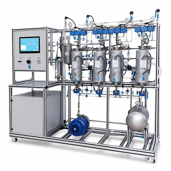
The critical requirements are clean, dry, stable, and reliably available compressed air. For pilot-plant instrumentation and controls, the air must be oil-free, cooled, and dried so moisture does not condense in tubing or damage pneumatic instruments. The system should use a suitable compressor arrangement, outside-air intake, filtration and drying, an air receiver to absorb demand fluctuations, and local pressure regulation at each instrument.
Instrument air is a control-system utility, not simply plant air. Its quality and pressure must remain within the requirements of the connected instruments, because contamination, condensation, or pressure instability can cause inaccurate control, failed actuators, or unsafe process behavior.
Why Instrument Air Quality Matters
Preventing moisture-related failures
Compressed air leaves the compressor hot and often contains significant water vapor. As it cools in the receiver and distribution piping, that vapor can condense and enter control valves, positioners, tubing, and other instruments.
The air should therefore be cooled and dried before distribution. Drainage points and appropriate moisture removal are also necessary wherever condensate can collect.
Controlling oil contamination
Oil carryover can foul pneumatic instruments, interfere with valve operation, and contaminate processes. The preferred solution is an oil-free compressor or a properly selected system designed to prevent oil from entering the instrument-air network.
Mist or coalescing filters can reduce oil carryover, but they should not automatically be treated as equivalent to an oil-free compressor. Filters require correct sizing, maintenance, and replacement; their performance also depends on the upstream compressor and the required air-quality level.
Providing suitable filtration
The air-treatment train should remove particulate and residual aerosols before the air reaches sensitive controls. Filtration must be matched to the compressor type, dryer, expected contamination, and instrument manufacturers’ requirements.
The objective is not merely clean-looking air. It is air that remains clean and dry throughout normal operation, including periods of changing demand.
Designing for Stable Pressure
Using an air receiver
A buffer storage tank, or air receiver, is a key part of the system. It smooths compressor cycling and short-term demand surges, helping prevent pressure dips when several pneumatic devices operate simultaneously.
The receiver also provides limited stored capacity during transient interruptions. It does not replace proper compressor capacity, drying, filtration, or a defined response to utility failure.
Establishing distribution pressure
A common pilot-plant arrangement maintains distribution pressure near 100 psi before reducing pressure locally. This value is a practical reference, not a universal requirement; the final pressure should be based on the connected instruments, actuators, tubing, and applicable equipment specifications.
Pressure should be reduced at or near each process instrument with a suitable regulator. Local regulation allows different devices to receive the pressure they require without making the entire utility network operate at unnecessarily high pressure.
Avoiding pressure fluctuations
Control valves and pneumatic actuators can create rapid, intermittent demand. The compressor, receiver, piping, and regulators must be selected so these events do not cause unacceptable pressure changes at critical instruments.
Pilot plants often have variable operating configurations, so the design should consider the maximum credible simultaneous demand rather than only the average consumption.
Locating and Arranging the Utility System
Drawing intake air from outside
The compressor intake should draw air from outside the building where practical. This reduces compressor noise and avoids repeatedly compressing conditioned room air.
The intake location must still be selected to avoid nearby contamination sources, such as exhaust discharges or areas where process vapors may accumulate. Intake protection and weather resistance are part of the installation design.
Keeping treatment equipment accessible
Compressors, receivers, filters, dryers, drains, and regulators require inspection and maintenance. They should be installed where operators and maintenance personnel can safely access them without disrupting unrelated pilot-plant activities.
Condensate drains and filter elements are especially important maintenance points. A system that meets its design specification only when its filters and drains are serviced is not reliable in practice unless that maintenance is managed.
Separating utility quality from process air quality
Instrument air and general-purpose service air should not be assumed to have identical quality requirements. Air used for pneumatic controls may require substantially better control of moisture and oil than air used for noncritical utility tasks.
If a common system serves both purposes, the design must ensure that general service demand or contamination does not compromise the instrument-air supply.
Supporting Safe Pilot-Plant Operation
Treating air failure as a process hazard
Loss of compressed air can cause control valves and actuators to move to their fail positions, remain where they are, or become unavailable. The required behavior depends on the process and must be considered in the control and safety design.
Critical functions should therefore have defined responses to low air pressure or total air loss. These responses should align with the process hazard analysis and the intended behavior of safety instrumented functions.
Validating alarms and interlocks
Pilot plants should test low-pressure alarms, control interlocks, and other protective functions associated with the compressed-air utility and the process. Testing should confirm that the system detects abnormal conditions and produces the intended safe response.
This is particularly important in educational and research facilities, where equipment may be operated by users with different levels of experience.
Inspecting pressure protection
The receiver and other pressurized components require appropriate pressure-relief protection and inspection. Pressure relief devices should be accessible and included in the facility’s inspection and maintenance program.
A reliable utility system is not only one that maintains pressure during normal operation. It must also be designed and maintained to limit the consequences of abnormal pressure conditions.
Understanding the Trade-offs
Oil-free compressors versus downstream filtration
Oil-free compressors reduce the risk of oil entering the air supply at its source, but they may involve different purchase, operating, or maintenance considerations. Compressors that use oil require effective separation and filtration, and downstream filters cannot be treated as maintenance-free safeguards.
The choice should be based on the required air quality, instrument sensitivity, lifecycle maintenance capability, and consequences of contamination.
Higher pressure versus efficient operation
Operating the distribution system near 100 psi can provide a useful margin for local regulation, but higher pressure is not automatically better. Excessive pressure can increase energy consumption, leakage losses, and stress on components.
Use the lowest stable distribution pressure that satisfies the connected equipment and the required transient performance.
Centralized utility versus local equipment
A centralized system simplifies distribution and can support multiple pilot units, but a failure may affect the entire facility. Local compressors or dedicated air treatment may improve independence for selected equipment, while increasing equipment count and maintenance effort.
The appropriate arrangement depends on the criticality of the process, the number of users, and the consequences of losing a common utility.
Standardization and maintainability
Standardizing regulators, filters, sensors, and related process-control equipment where technically appropriate simplifies operator training and spare-parts management. It also makes preventive maintenance more consistent across pilot-plant units.
Standardization should not override instrument-specific requirements. Common parts are valuable only when they remain suitable for the required pressure, air quality, and service conditions.
How to Apply This to Your Pilot Plant
The final design should be checked against instrument manufacturers’ requirements and the process safety assessment.
- If your primary focus is air quality: Use an oil-free source or a properly engineered oil-removal system, then cool, dry, and filter the air before it reaches the instruments.
- If your primary focus is pressure stability: Provide an adequately sized air receiver, size the compressor and piping for peak simultaneous demand, and regulate pressure locally at each instrument.
- If your primary focus is reliability: Use an accessible system with maintainable filters and drains, an outside-air intake, and defined responses to low pressure or total air loss.
- If your primary focus is operator and personnel safety: Validate alarms, interlocks, pressure-relief devices, and fail-safe responses as part of the pilot plant’s safety and commissioning program.
- If your primary focus is lifecycle cost: Standardize compatible components and maintenance practices without compromising the air-quality or pressure requirements of individual instruments.
A well-designed instrument-air system gives the pilot plant a stable control foundation: clean air for accuracy, dry air for reliability, and dependable pressure for safe operation.
Summary Table:
| Requirement | Recommended approach | Benefit |
|---|---|---|
| Air quality | Use an oil-free compressor or engineered oil-removal system with suitable filtration | Protects instruments from oil and particulate contamination |
| Moisture control | Cool, dry, and drain compressed air before distribution | Prevents condensation, corrosion, and instrument failure |
| Pressure stability | Size the compressor, piping, and receiver for peak simultaneous demand | Reduces pressure dips during actuator and valve operation |
| Local regulation | Install pressure regulators near individual instruments | Matches supply pressure to equipment requirements |
| System reliability | Provide accessible filters, drains, alarms, and defined low-pressure responses | Supports maintainability and dependable operation |
| Safety protection | Protect receivers with pressure-relief devices and validate alarms and interlocks | Limits abnormal-pressure hazards and supports safe shutdown |
| Utility arrangement | Evaluate centralized versus local compressors based on process criticality | Balances facility-wide coverage, independence, and maintenance effort |
Planning a reliable pilot-plant utility system? Contact LABPARK to discuss your requirements. LABPARK provides Educational and Vocational Unit Operations Pilot Plants for chemical engineering, bioprocess and biotech, and environmental and water treatment applications. Our solutions help universities, research institutes, and enterprises build safe, maintainable training and research environments with suitable process instrumentation, control systems, and utility integration.
Related Products
- Carbon Dioxide Capture and Utilization Educational Pilot Plant for Unit Operations
- Multifunctional Membrane Separation Educational Pilot Plant with Ultrafiltration, Nanofiltration, Reverse Osmosis
People Also Ask
- What are the differences between post- and pre-combustion carbon capture training pilot plants?
- How can pilot plants show tail gas vs flue gas CO2 capture differences? Key educational insights.
- What unit operations are critical for CCUS training pilot plants? Build hands-on engineering expertise.
- How do temperature variations affect CO2 transport models in pilot plants? Model vs Reality
- How does operating pressure influence the transition between absorption and desorption in a CO2 pilot plant?