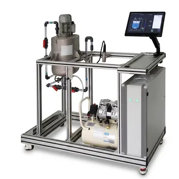
Most agitation challenges in a pilot plant are solved by matching the impeller’s flow pattern to where your fluid sits on the viscosity scale—and then scaling that choice to your vessel’s size. This choice is the single biggest lever you have to ensure that the heat transfer, mass transfer, and blending data you collect in your pilot plant will faithfully represent what will happen in the full-scale process.
The type of agitator is selected by first identifying whether your fluid is low- or high-viscosity under process conditions, then pairing that regime with an impeller that generates either turbulent, high-shear flow (turbines or propellers) or laminar, positive-displacement mixing (anchors or helical ribbons). The vessel volume then dictates the impeller diameter, the number of impellers, and the necessary power input, ensuring uniform conditions throughout the pilot-scale unit without creating dead zones or excessive shear.
Mapping Viscosity and Vessel Volume: The Foundation of Impeller Selection
Agitator selection in a pilot plant is not a catalog lookup; it is a deliberate decision that links fluid rheology to the mixing regime and the physical scale of the experiment. You will always want to start by placing your fluid on a viscosity-versus-volume map.
The Reynolds Number Decides the Flow Regime
Every agitator selection begins with a single, unifying question: will the flow be turbulent or laminar?
For low-viscosity fluids (typically below about 100 mPa·s, like water, light solvents, or dilute aqueous solutions), the mixing Reynolds number will be well above 10,000. In this turbulent regime, the impeller’s job is to convert shaft power into rapid fluid motion that disperses and blends.
Here, you want impellers that create either axial flow (top-to-bottom turnover) or radial flow (high-shear, wall-directed streams). Propellers and pitched-blade turbines deliver strong axial flow and are the workhorse for bulk blending. Flat-blade turbines (Rushton-type) generate intense radial flow and excel when high local shear is needed, such as in gas dispersion or liquid–liquid break-up.
Low-Viscosity Fluids: Turbines and Propellers for High Reynolds Number Operation
For pilot-scale vessels processing thin liquids, the selection rule is straightforward: use high-speed impellers with diameters smaller than half the tank diameter.
- Axial flow impellers (marine propellers, pitched-blade turbines) provide excellent top-to-bottom turnover at low power input. They are preferred for simple blending, solids suspension, and heat transfer to a jacketed wall because they push fluid along the vessel floor and up the walls.
- Radial flow impellers (flat-blade disc turbines) are chosen when high shear or gas dispersion is the controlling process requirement. They create a strong, outward radial jet that breaks bubbles and droplets but give poorer vertical blending unless multiple impellers are stacked.
For a pilot plant, you will often combine an axial-flow impeller for bulk motion with a small radial turbine if a specific high-shear duty exists in the same vessel.
High-Viscosity Fluids: The Domain of Close-Clearance Impellers
Once viscosity rises above roughly 10–50 Pa·s (10,000–50,000 cP), the flow regime shifts to laminar. High-speed impellers simply create a cavern of moving fluid around the blade, leaving the rest of the vessel stagnant. The mixing mechanism must change from fluid inertia to positive mechanical displacement.
This is where close-clearance, low-speed impellers dominate. Anchor impellers sweep the vessel wall and scrape it clean, promoting heat transfer and preventing dead layers. Helical ribbon impellers combine wall scraping with a strong vertical pumping action in viscous media, giving much better top-to-bottom blending than a simple anchor. Paddle impellers provide a simpler, bulk-motion effect for moderately viscous pastes and slurries.
In a pilot plant, the helical ribbon is often the definitive choice for true high-viscosity processing because it mimics the pumping characteristics you will need in production-scale reactors, where heat transfer and thorough blending are paramount.
Transition Region: Special Considerations for Pilot Plants
For fluids in the intermediate range (roughly 100 mPa·s to 10 Pa·s), the Reynolds number can fall into the transitional zone where turbulence decays but true laminar mixing is not yet fully developed. In a pilot plant, this is the most dangerous zone for scale-up.
High-efficiency axial impellers (like hydrofoils) can still perform well, but you must verify that the flow reaches the wall and that cavern formation is not occurring. Often, you will need to increase the impeller diameter relative to the tank (pushing D/T closer to 0.4–0.6) and consider using a baffle configuration that promotes shear thinning without completely dampening the flow. The pilot plant is your tool to experimentally map this transition before committing to a full-scale design.
How Vessel Volume Shapes Agitator Configuration
Viscosity tells you which family of impellers to use; vessel volume and geometry tell you how many and what size.
Impeller Diameter-to-Tank Ratio and the Number of Impellers
In low-viscosity pilot vessels (up to about 200 L), a single impeller with D/T ≈ 0.3–0.4 placed one impeller diameter off the bottom can often provide adequate blending. But as the liquid height exceeds the tank diameter, a single impeller leaves the top portion poorly mixed.
The rule for pilot plants is: when the liquid height-to-diameter ratio (H/T) is greater than 1.2–1.5, you must use multiple impellers spaced at intervals of roughly one impeller diameter. This is critical for both blending uniformity and heat transfer. Each impeller generates its own circulation loop, and the combined flow keeps the entire volume active.
For high-viscosity systems, a single close-clearance impeller that spans the entire liquid height is common. Helical ribbons, for example, are fabricated to extend nearly the full filling height, so one element covers the entire volume. Volume scaling for these systems is about maintaining the same tip speed and the same close wall clearance, not about stacking impellers.
Ensuring Uniform Heat and Mass Transfer at Pilot Scale
Your pilot plant exists to provide scalable data. Heat transfer coefficients, mass transfer rates, and blending times are all functions of the power input per unit volume.
When you scale up a low-viscosity process, you often aim to keep the power per volume (P/V) constant. In a pilot vessel, this means you select an impeller type and diameter that, at a given shaft speed, deliver the P/V you will target at scale. Vessel volume directly enters this calculation: a larger pilot vessel may demand a larger impeller or a higher speed to achieve the same intensity. The viscosity–volume map helps you verify that the chosen impeller will not leave quiescent corners that corrupt your heat transfer coefficient measurements.
Understanding the Trade-offs and Common Pitfalls
No single impeller type is universally optimal. The most authoritative selection still involves honest compromises that a pilot-plant operator must navigate.
The Trap of One-Size-Fits-All for Low-Viscosity Systems
A flat-blade turbine looks capable in a glass-walled pilot reactor, but if your primary need is blending and heat transfer, the radial flow pattern will waste energy and produce a poorer overall turn-over than a pitched-blade turbine. The pilot plant can then misrepresent the blending time at scale, leading to an underestimation of mixing constraints in the production design.
Overlooking Shear Sensitivity When Switching to High-Shear Impellers
Some biological or polymeric fluids are shear-sensitive. Using a Rushton turbine in a low-viscosity pilot fermenter can generate damaging local shear rates near the blade tips, while an axial-flow hydrofoil provides gentler, bulk motion. The viscosity-volume map alone does not capture this; you must overlay the biological or material constraints. In piloting, a shear-sensitivity test is as important as the viscosity measurement.
The Danger of Insufficient Wall Coverage for Heat Transfer in High-Viscosity Mixing
An anchor impeller provides excellent wall scraping but very little vertical turnover. If your pilot reactor is tall and relies on jacket heat transfer, the bulk temperature may stratify because the anchor only renews the fluid near the wall, without pulldown of the center core. That is why a helical ribbon—which mechanically pumps downward at the wall and upward in the center—is so often preferred, even though it is more complex to fabricate for a small pilot vessel.
Making the Right Choice for Your Pilot Plant Goal
The correct agitator emerges from the intersection of your pilot plant’s main objective and the fluid’s behavior under realistic conditions. Use these goal-driven rules to cut through the complexity after you have mapped viscosity and volume.
- If your primary focus is rapid bulk blending of a low-viscosity solvent or solution: Choose a pitched-blade turbine or marine propeller sized for strong axial flow, with a D/T ratio around 0.3–0.4 and add a second impeller if H/T exceeds 1.2.
- If your primary focus is gas dispersion or a fast liquid–liquid reaction requiring high mass transfer: Select a flat-blade disc turbine (Rushton-type) for radial high-shear, and consider stacking it with an axial impeller above to maintain top-to-bottom turnover; confirm the agitation scale (6–10) to avoid flooding.
- If your primary focus is uniform heating or cooling of a moderately viscous polymer solution or paste: Use a close-clearance anchor impeller with a wall scraper, but pair it with a concentric off-center propeller or an internal draft tube if vertical blending deadlines are indicated.
- If your primary focus is reliable scale-up of a true high-viscosity (>10 Pa·s) reacting system: Invest in a helical ribbon impeller that fully spans the working height; this gives you both positive wall renewal and the pumping capacity needed to keep a uniform temperature and concentration profile at any pilot scale.
Your pilot plant agitator is a precision instrument for generating transferable engineering data—match its type first to your fluid’s viscosity, then to the vessel’s volume, and you will capture the realities that a full-scale design must confront.
Summary Table:
| Impeller Type | Viscosity Range | Flow Pattern | Best For |
|---|---|---|---|
| Propeller / Pitched-Blade | Low (<100 mPa·s) | Axial | Bulk blending & heat transfer |
| Rushton / Flat-Blade | Low (<100 mPa·s) | Radial | Gas dispersion & high-shear mixing |
| Hydrofoil / Large Axial | Medium (0.1–10 Pa·s) | Transitional | Gentle mixing in transition zones |
| Anchor | High (>10 Pa·s) | Tangential | Wall scraping & jacket heat transfer |
| Helical Ribbon | High (>10 Pa·s) | Laminar / Positive | High-viscosity blending & scale-up |
Optimize Your Pilot Plant Operations with LABPARK
Selecting the right mixing configuration is critical for reliable process scale-up. LABPARK designs and provides premium Educational and Vocational Unit Operations Pilot Plants in chemical engineering, bioprocess & biotech, and environmental & water treatment tailored for universities, research institutes, and enterprises.
Need help configuring the perfect agitator or pilot system for your lab? Contact our experts today to discuss your specific process requirements!
Related Products
- Agitation and Mixing Educational Unit Operations Pilot Plant
- Two Phase Flow Pattern Velocity Resistance Measurement Educational Pilot Plant
People Also Ask
- Why is the Reynolds number ($Re_M$) critical in mixing? Master N_P for pilot plants.
- What are the four guiding principles of process intensification? Educational Equipment Guide
- How do educational unit operations pilot plants support process analysis? Connect theory with real data
- How does the pseudobinary diffusion approximation simplify mass transport equations in educational pilot plants?
- Why is post-implementation performance evaluation and gap analysis critical when deploying educational unit operations pilot plants?