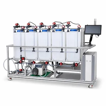
Your packed-bed electrochemical reactor’s performance is ultimately capped by the product of its specific interfacial area and mass transfer coefficient.
For mass-transfer-limited reactions—common in electrochemical waste-treatment pilots—the maximum achievable reaction rate (the limiting current density) is directly proportional to the product of the specific interfacial area, a, and the mass transfer coefficient, k_m. In simple terms, a defines how much reactive electrode surface you have per unit volume, while k_m describes how fast reactants travel from the bulk solution to that surface. Optimizing this a × k_m product is the central lever for maximizing conversion efficiency, reducing reactor volume, and scaling up successfully.
The core lever in any packed-bed electrochemical pilot plant is the product
a × k_m. It sets the hard ceiling on reaction rate for mass-transfer-limited systems. Everything—electrode geometry, flow rate, temperature—either increases or decreases this product, which directly governs throughput and conversion.
The Fundamental Relationship: Why a × k_m Defines Your Reactor’s Ceiling
In an electrochemical reactor, a reaction can only proceed as fast as reactants reach the electrode surface. When electron transfer is fast relative to transport, the process becomes mass-transfer-limited. At that point, the limiting current density per unit of available electrode area is i_L = n F k_m C_bulk. But in a three-dimensional packed bed, the total available area is a times the reactor volume V. The overall reaction rate for the reactor therefore scales as a × k_m. Doubling either parameter doubles the achievable throughput for a given reactor size and conversion target. That is why pilot-plant scale-up studies obsess over measuring and enhancing this product.
How the Specific Interfacial Area (a) Determines Reactor Capacity
The specific interfacial area, a, represents the electrochemically active surface area per unit reactor volume. In a packed-bed electrode, this is dictated by the geometry and material of the packing. Finer particles, porous substrates, or high-roughness coatings can push a into the thousands of square meters per cubic meter. In practice, a is proportional to (1 – porosity) / d_p, where d_p is the characteristic particle size. Smaller particles pack more surface area into the same volume, but at the cost of increased pressure drop and a greater risk of channeling or clogging during long-term operation.
How the Mass Transfer Coefficient (k_m) Sets the Speed of Reactant Delivery
k_m captures how effectively fluid motion sweeps reactants from the bulk to the electrode surface. It is governed by the local hydrodynamics—flow velocity, turbulence, and fluid properties (viscosity, diffusivity). In packed beds, empirical correlations like Sh = constant · Re^α Sc^β link k_m to the Reynolds and Schmidt numbers. Practically, increasing the liquid flow rate or inserting turbulence-promoting spacers raises k_m dramatically, but also increases energy consumption and pumping requirements. Temperature also plays a crucial role: higher temperatures reduce viscosity and increase diffusion coefficients, boosting k_m with minimal pumping penalty.
Why the Product Matters More Than Either Term Alone
A high a with poor mass transfer (low k_m) starves the electrode of reactants; a high k_m with low a wastes transport capacity. The product a × k_m is the multiplier that directly determines the volumetric reaction rate, and therefore the reactor’s space-time yield. Pilot plants allow you to vary packing size (changing a) and flow conditions (changing k_m) independently, revealing the synergistic effect. For example, switching from 10 mm to 5 mm packing might double a while only slightly reducing k_m due to altered flow patterns, leading to a nearly doubled overall production rate at the same flow.
Measuring a and k_m in a Pilot-Plant Setting
Pilot-scale packed-bed electrochemical reactors make it practical to measure these parameters directly:
acan be determined via mercury porosimetry, BET surface area measurements, or—more relevantly—by electrochemical methods such as the adsorption charge of a known redox probe.k_mis routinely extracted from limiting current experiments using a fast, well-behaved redox couple (e.g., ferri-/ferrocyanide). By measuring the plateau current at varying flow rates, you can back-calculatek_mand validate empirical correlations. This experimental capability is what transforms a pilot plant from a simple scale-up tool into a platform for building accurate predictive models.
Understanding the Trade-offs
Optimizing a × k_m is not a one-way street. Each parameter carries penalties:
- Pressure drop vs. surface area: Increasing
aby using finer packing inevitably raises the pressure drop across the bed, potentially requiring larger pumps and increasing operating costs. At some point, the energy penalty outweighs the conversion gain. - Flow maldistribution and dead zones: Very high
apacks can create preferential flow channels that bypass large portions of the electrode, undermining the apparent advantage. Uniform flow distribution—often achieved through careful distributor design—is critical. - Electrical potential distribution: In a packed-bed electrode, current distribution can become uneven if the electronic conductivity of the bed is insufficient. High local reaction rates near the current collector can lead to hot spots, while areas far from the collector remain underutilized.
- Maintenance and longevity: Fine packings are more susceptible to fouling and solids accumulation in real wastewater streams, raising maintenance frequency and reducing long-term reliability.
Balancing these trade-offs requires pilot-scale testing under realistic feed conditions, not just clean laboratory solutions.
Making the Right Choice for Your Goal
Your pilot-plant optimization roadmap should be guided by the primary objective:
- If your primary focus is maximizing throughput per unit volume: Increase both
a(smaller, high-surface-area electrode packings) andk_m(higher flow rates, turbulence promoters) while staying within your pump and pressure-drop budget. Monitor maldistribution carefully. - If your primary focus is high single-pass conversion with low energy cost: Select a packing that gives a long residence time and moderate
a, then tune flow to achieve the necessaryk_mwithout excessive pumping. This minimizes pressure drop and pumping energy. - If your primary focus is generating scale-up correlations and kinetic data: Operate under conditions where mass transfer resistance is negligible relative to reaction kinetics, then independently measure
k_mto decouple transport from intrinsic kinetics. Vary packing sizes systematically to verify thea × k_mproportionality. - If your primary focus is treating real, particle-laden wastewater: Prioritize larger channel sizes and a design that resists fouling. You may accept a lower
ato maintain consistentk_mover long campaigns, rather than chasing the highest possible initial product.
Every decision you make about electrode geometry, flow rate, and temperature ultimately changes the a × k_m product—and therefore the heart of your reactor’s performance. Focus your pilot-plant experiments on measuring and maximizing this product within your system’s practical limits to achieve the scale-up that actually works.
Summary Table:
| Parameter | Key Role in Reactor | Primary Optimization Trade-off |
|---|---|---|
| Specific Interfacial Area ($a$) | Defines the active electrode surface area per unit reactor volume. | Higher $a$ (finer packing) increases reaction sites but raises pressure drop and clogging risks. |
| Mass Transfer Coefficient ($k_m$) | Governs how fast reactants are transported from bulk fluid to the electrode surface. | Higher flow velocities boost $k_m$ but significantly increase pumping energy consumption. |
| The Product ($a \times k_m$) | Sets the hard ceiling on the volumetric reaction rate for mass-transfer-limited systems. | Must balance packing size and flow dynamics to prevent maldistribution and dead zones. |
Optimize Your Electrochemical Scale-Up with LABPARK
Are you looking to bridge the gap between laboratory research and industrial-scale electrochemical processes? LABPARK provides state-of-the-art Educational and Vocational Unit Operations Pilot Plants in chemical engineering, bioprocess & biotech, and environmental & water treatment.
Designed specifically for universities, research institutes, and enterprises, our pilot plants empower you to precisely control, measure, and optimize critical reactor parameters like $a \times k_m$, flow hydrodynamics, and packing configurations.
Let us help you design, test, and scale your electrochemical systems with reliability and precision. Contact LABPARK today to discover how our pilot plant solutions can elevate your research and engineering training!
Related Products
- Micro-Scale Gas-Solid Catalytic Reaction Educational Pilot Plant
- Packed Bed Absorption Educational Unit Operations Pilot Plant
- Fixed-Bed Chemical Reaction and Gas Dust Tar Removal Unit Operations Pilot Plant
- High-Gravity Emulsification and Mass Transfer Educational Pilot Plant
- Multi Functional Catalytic Reaction and Reactor Evaluation Educational Unit Operations Pilot Plant
People Also Ask
- How to determine catalyst pore radius & porosity? Optimize your chemical engineering pilot plant.
- 1D vs 2D Catalytic Reactor Models: What Are the Practical Trade-Offs?
- How does identifying the rate-limiting step optimize reaction conditions? Pilot Plant Guide
- What reactor configurations study gas-solid reactions? Guide to key types and applications.
- Why Control WHSV & Residence Time in Catalytic Reactor Pilot Plants? Optimize Yield